INTAKE AND EXHAUST VALVE CLEARANCE (INSPECT AND ADJUST)
<2.4L ENGINE>
Required Special Tools:
- MB992854: Magnet base plate
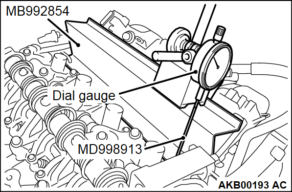
- MD998913: Dial gauge extension
| note | The intake valve side has the intake continuous variable valve lift system. The oil clearance between the arm and the shaft makes it difficult to measure the valve clearance with the usual feeler gauge. Therefore, use the dial gauge and check the amount of valve lift. |
1. Let the engine be in cold state.
2. Turn the ignition switch to the "LOCK" (OFF) position.
3. Remove the rocker cover assembly.
4. Install the special tool MB992854 to the upper face of the cylinder head at the intake side.
| note | At that time, remove the injector connector and the fixed portion of the harness bracket so that the engine harness cannot interfere with the installation. |
5. Install the special tool MD998913 to the dial gauge.
6. When installing the dial gauge to the magnet base plate, the dial gauge must have almost the same angle as the intake valve has.
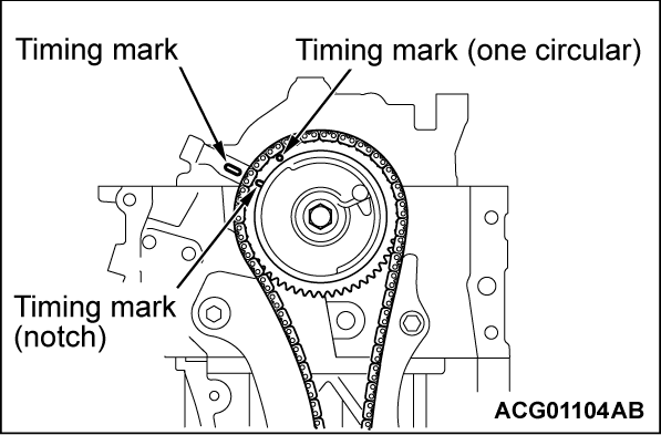
7. Rotate the crankshaft clockwise and align the timing mark of the rocker shaft holder with the timing mark (notch) of the V.V.T. sprocket. Therefore, the No. 1 cylinder is set at the top dead center on its compression stroke.
8. For the No. 1 cylinder intake valve, check and adjust the valve clearance according to the following procedures.
9.
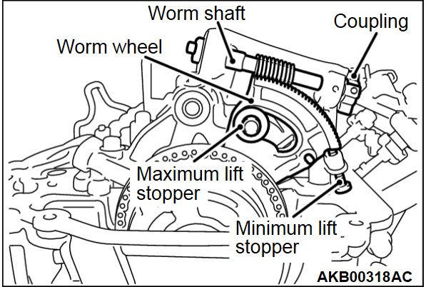
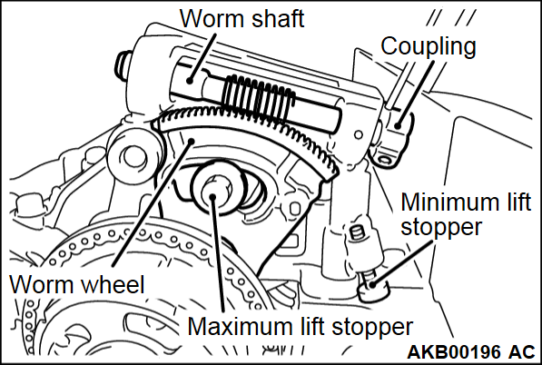
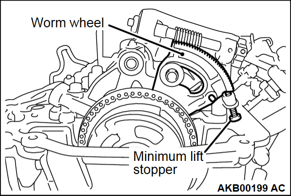
Slowly rotate the coupling clockwise. When lightly touching the worm wheel to the minimum lift stopper, stop the worm wheel at the position shown in the illustration.
| caution |
|
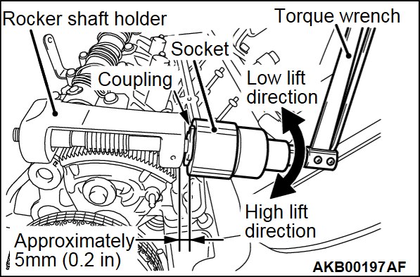
| note | When rotating the coupling clockwise, the worm wheel should move in the minimum lift direction. When rotating the coupling counterclockwise, the worm wheel should move in the maximum lift direction. |
| note | When manually rotating the coupling, insert a 12-point socket (24 mm) into the position on the coupling approximately 5 mm (0.2 inch) away from the rocker shaft holder. Connect the mini torque wrench and slowly rotate them. |
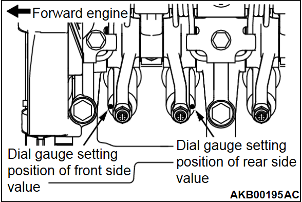
10. Set the dial gauge on the upper face of the valve spring retainer at the forward engine side. Set the dial gauge to 0.
| note | As shown in the illustration, prevent the measurement error caused by the tilted valve, install the rocker arm to the outside of the rocker arm. |
11.
Slowly rotate the coupling. Place the worm wheel as shown in the illustration so that the center of the worm wheel gear can engage with the worm shaft (at around the middle lift position).
| caution |
|
| note | When rotating the coupling clockwise, the worm wheel should move in the minimum lift direction. When rotating the coupling counterclockwise, the worm wheel should move in the maximum lift direction. |
12.
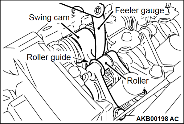
Pushing the feeler gauge with 0.15 mm(0.006 inch) in thickness between the swing cam and the roller of the rocker arm, rotate the coupling clockwise. Rotate the worm wheel to the minimum lift side. Insert the feeler gauge top by approximately 5 mm(0.2 inch).
| caution |
|
| note | If not easily inserting the feeler gauge, you can insert the feeler gauge more easily by rotating the crankshaft clockwise 2 revolutions with pushing the feeler gauge. |
| caution | Do not forcibly push the worm wheel to the minimum lift stopper. |
13. Check the worm wheel stopping at the position, as shown in the illustration, lightly touching to the minimum lift stopper. Check that the feeler gauge is securely inserted.
14. Check that the dial gauge reading is within the standard value.
Standard value: -0.11 ± 0.03 mm (-0.004 ± 0.001 inch)
| note | By inserting the 0.15 mm(0.006 inch) feeler gauge, the 0.26 mm(0.010 inch)-stroke occurs at the rocker arm adjusting screw side. Therefore, the valve clearance at the intake side can be calculated by the following calculating formula using the dial gauge reading. |
Calculating formula:
- valve clearance = 0.26 mm(0.010 inch) + (dial gauge reading)
- <Example> If the dial gauge reading is -0.11 mm(-0.004 inch),
- valve clearance = 0.26 mm + (-0.11) = 0.15 mm [0.010 inch + (-0.004) = 0.006 inch]
15. If the dial gauge reading is not within the standard value, perform the adjustment according to the following procedures.
16. Loosen the rocker arm lock nut at the forward engine side. Pull up the adjusting screw once. From the upper portion of the adjusting screw, sufficiently apply the engine oil between the lower adjusting screw end and the valve axis end so that the engine oil can be provided enough. And then, perform the adjustment by rotating the adjusting screw so that the dial gauge can read -0.11 mm(-0.004 inch).
17. After the adjustment, hold the driver to prevent the adjustment screw from rotating. Temporarily tighten the lock nut. Rotate the coupling counterclockwise. Return the worm wheel to around the middle lift position. Pull out the feeler gauge.
18. For the valve at the backward engine side, check the valve clearance in the same procedure as that of the valve at the forward engine side. If the valve clearance is not within the standard value, perform the adjustment in the same procedure as that of the valve at the forward engine side.
19. After the adjustment, hold the driver to prevent the adjustment screw from rotating. Tighten the lock nut to the specified torque. And then, check that the dial gauge reading does not change.
Tightening torque: 9.0 ± 1.0 N·m (80 ± 8 in-lb)
20. Check again the valve clearance at the forward engine side. If the valve clearance is not within the standard value, perform the adjustment in the same procedure as the first adjustment.
21. After the adjustment, hold the driver to prevent the adjustment screw from rotating. Tighten the lock nut to the specified torque. And then, check that the dial gauge reading does not change.
Specified torque: 9.0 ± 1.0 N·m (80 ± 8 in-lb)
22. Rotate the coupling counterclockwise. Return the worm wheel to around the middle lift position. Pull out the feeler gauge.
23. For the No. 2 cylinder intake valve, check and adjust the valve clearance according to the procedures from Step 9 to Step 22.
24. For the No. 1 and No.3 cylinder exhaust valves, check and adjust the valve clearance according to the following procedures.
25. Insert the feeler gauge between the exhaust valve axis end and the adjusting screw. Measure the valve clearance.
Standard value: 0.20 ± 0.03 mm (0.008 ± 0.001 inch)
26. If the valve clearance is not within the standard value, loosen the lock nut. Adjust the adjusting screw so that the valve clearance can be within the standard value.
27. After the adjustment, hold the driver to prevent the adjustment screw from rotating. Tighten the lock nut to the specified torque.
Tightening torque: 9.0 ± 1.0 N·m (80 ± 8 in-lb)
28. Rotate the crankshaft clockwise once. Align the crankshaft pulley timing mark (notch) with the "T" mark of the timing chain case. Therefore, the No. 4 cylinder is set at the top dead center on its compression stroke.
29. For the No. 3 cylinder intake valve, check and adjust the valve clearance according to the procedures from Step 9 to Step 22.
30. For the No. 4 cylinder intake valve, check and adjust the valve clearance according to the procedures from Step 9 to Step 22.
31. For the No. 2 and No. 4 cylinder exhaust valves, check and adjust the valve clearance according to the procedures from Step 25 to Step 27.
32. Remove the special tool and return the engine harness to the original state.
33. Install the rocker cover assembly.
<3.0L ENGINE (INTAKE SIDE ONLY)>
| note | Perform the valve clearance check and adjustment at the engine cold state. |
1. Remove all of the ignition coils.
2. Remove the rocker cover.
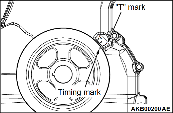
3. Turn the crankshaft clockwise until the notch on the pulley is lined up with the "T" mark on the timing indicator.
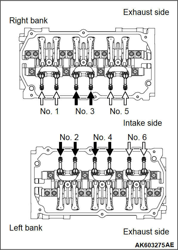
4. Valve clearance inspection and adjustment can be performed on rocker arms indicated by white arrow mark when the No. 1 cylinder piston is at the top dead center on the compression stroke, and on rocker arms indicated by black arrow mark when the No. 4 cylinder piston is at the top dead center on the compression stroke.
| note | If the rocker arm of No. 6 cylinder at the intake side is moved up and down and the rocker arm is moved, No. 1 cylinder is at top dead center on compression stroke. If the rocker arm of No. 6 cylinder at the intake side is moved up and down and the rocker arm is not moved, No. 4 cylinder is at top dead center on compression stroke. |
5. Measure the valve clearance for intake side.
If the valve clearance is not as specified, loosen the rocker arm lock nut and adjust the clearance using a thickness gauge while turning the adjusting screw.
Standard value (cold engine): 0.10 mm (0.004 inch)
| note | Valve clearance check and adjustment is unnecessary for exhaust side due to auto lash adjuster installed. |
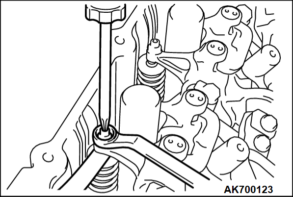
6. While holding the adjusting screw with a screwdriver to prevent it from turning, tighten the lock nut to the specified torque.
Tightening torque: 9 ± 1 N·m (80 ± 9 in-lb)
7. Turn the crankshaft 360 degrees to line up the notch on the crankshaft pulley with the "T" mark on the timing indicator.
8. Repeat steps 5 and 6 on other valves for clearance adjustment.
9. Install the rocker cover.
10. Install the ignition coils.
![[Previous]](../../../buttons/fprev.png)
![[Next]](../../../buttons/fnext.png)
