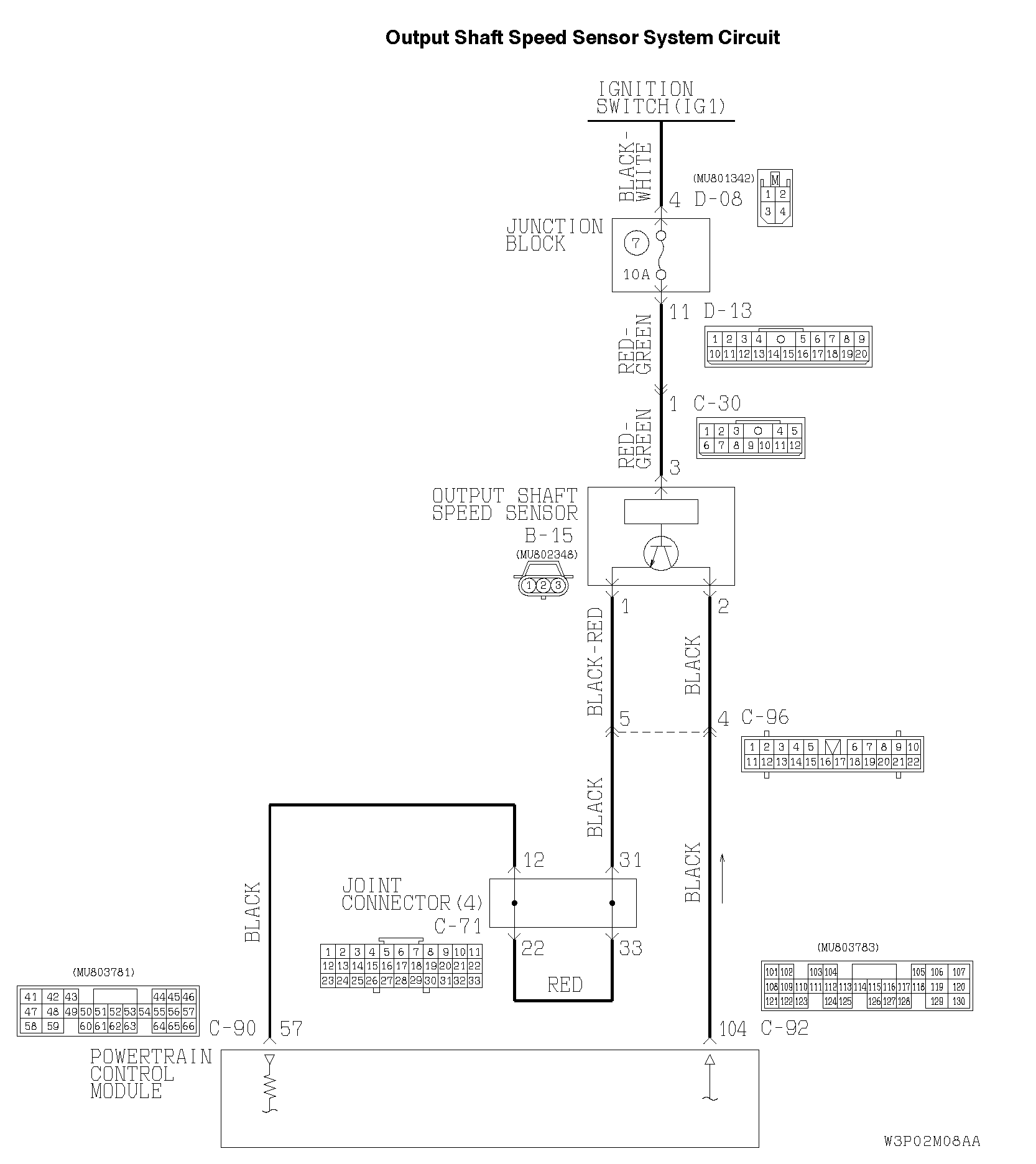
CIRCUIT OPERATION
The output shaft speed sensor generates a 0 <=> 5 volt pulse signal when the output shaft rotates. The pulse signal frequency increases with a rise in output shaft speed.
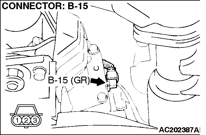
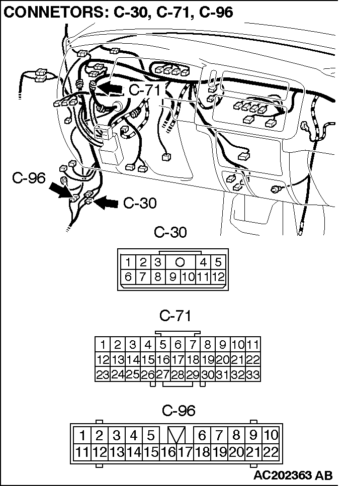
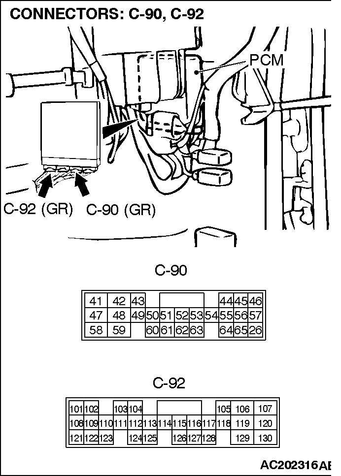
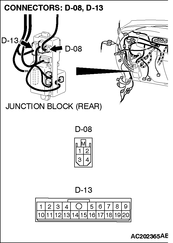
The output shaft speed sensor is connected to the PCM (terminals 57 and 104) via the output shaft speed sensor connector (terminals 1 and 2).
The PCM detects the output shaft speed by the signal input to terminal 104.
The output shaft speed sensor generates the pulse signal as the teeth of the output shaft pass the magnetic tip of the sensor. DESCRIPTIONS OF MONITOR METHODS
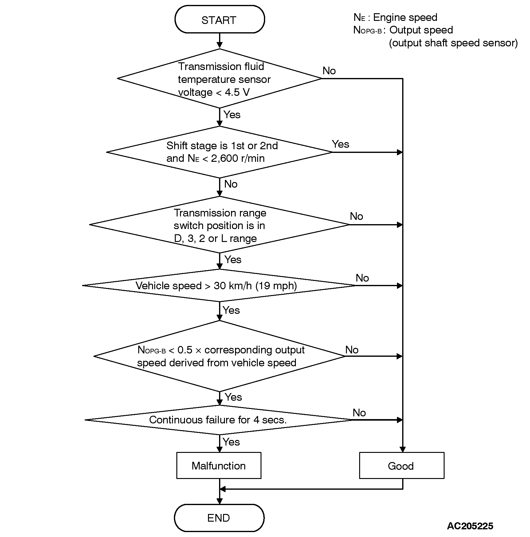
During driving test at more than specified speed, if vehicle speed calculated from output revolution is below half of vehicle speed from vehicle speed sensor, PCM judges that output shaft speed sensor circuit is open. MONITOR EXECUTION
Continuous MONITOR EXECUTION CONDITIONS (Other monitor and Sensor)
Other Monitor (There is no temporary DTC stored in memory for the item monitored below)
• DTC 29 (P0500): Vehicle speed sensor malfunction
Sensor (The sensor below is determined to be normal)
• Vehicle speed sensor LOGIC FLOW CHARTS (Monitor Sequence) DTC SET CONDITIONS
Check Conditions
Transmission range switch position: D, 3, 2 or L.
Vehicle speed: 30 km/h (19 mph) or more.
Transmission fluid temperature sensor voltage: 4.5 volts or less.
Judgement Criteria
Output shaft speed sensor signal: [0.5 x calculated output speed derived from vehicle speed] or less. (4 seconds)
If DTC 23 (P0720) is set consecutively four times, the transmission is locked into 3rd gear or 2nd gear as a fail-safe measure, and the "N" range light flashes once per second. OBD-II DRIVE CYCLE PATTERN
Start the engine, shift to 3rd gear or higher, and drive at 40 km/h (25 mph) or more for 4 seconds. TROUBLESHOOTING HINTS (The most likely causes for this code to be set:
Malfunction of the output shaft speed sensor
Malfunction of the output shaft
Damaged harness, connector
Malfunction of the PCM
![[Previous]](../../../BUTTONS/fprev.png)
![[Next]](../../../BUTTONS/fnext.png)