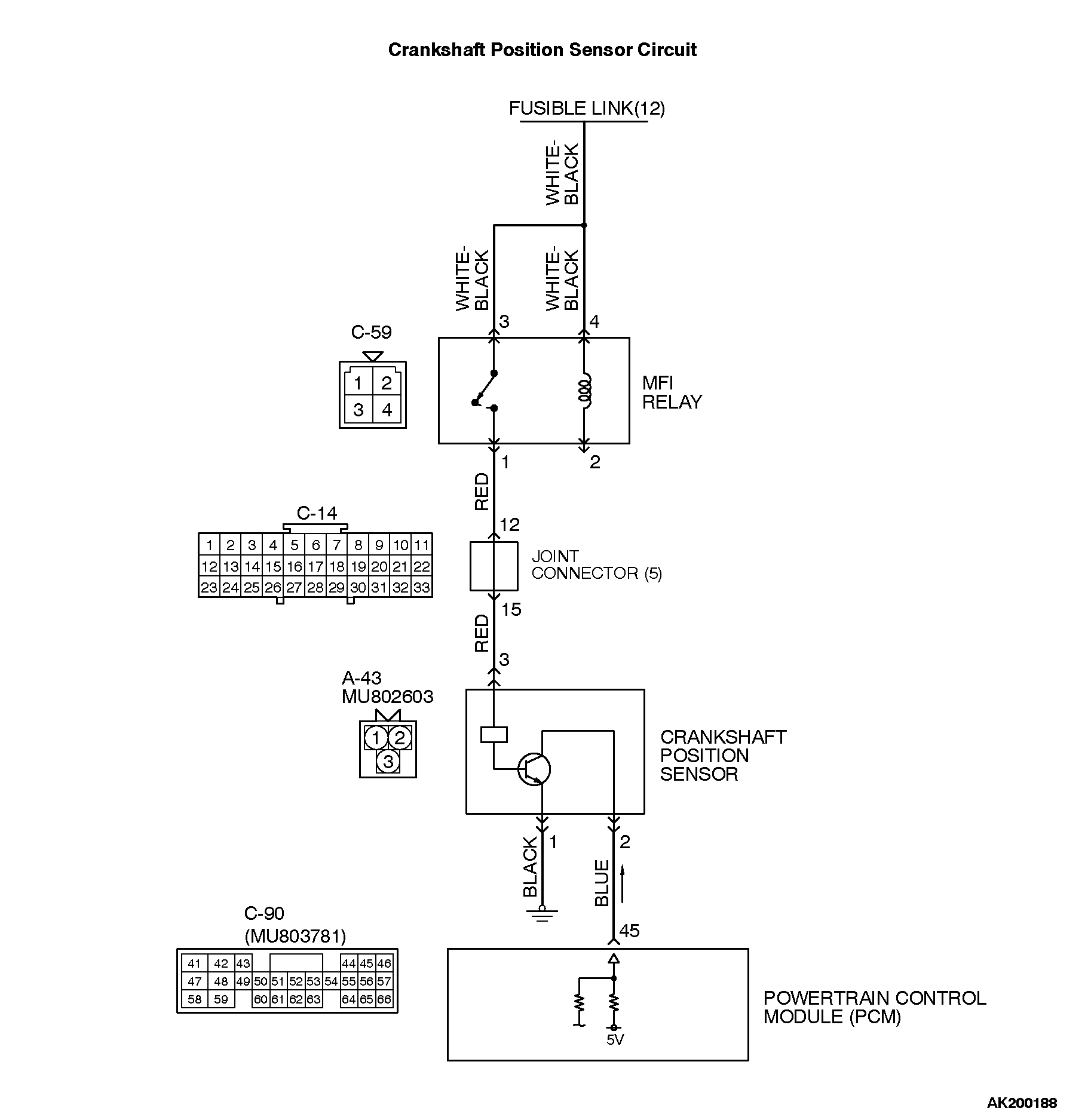
CIRCUIT OPERATION
• The crankshaft position sensor power is supplied from the MFI relay (terminal No. 1), and the ground is provided on the vehicle body.
• A 5-volt voltage is applied on the crankshaft position sensor output terminal (terminal No. 2) from the PCM (terminal No. 45). The crankshaft position sensor generates a pulse signal when the output terminal is opened and grounded. TECHNICAL DESCRIPTION
• The crankshaft position sensor detects the crank angle (position) of each cylinder, and converts that data to pulse signals, which are then input to the PCM.
• When the engine is running, the crankshaft position sensor outputs a pulse signal.
• The PCM checks whether pulse signal is input while the engine is cranking. DESCRIPTIONS OF MONITOR METHODS
• Crankshaft position sensor signal does not change.
• Crankshaft position sensor signal is not normal pattern. MONITOR EXECUTION
Continuous MONITOR EXECUTION CONDITIONS (Other monitor and Sensor)
Other Monitor (There is no temporary DTC stored in memory for the item monitored below)
• Not applicable
Sensor (The sensor below is determined to be normal)
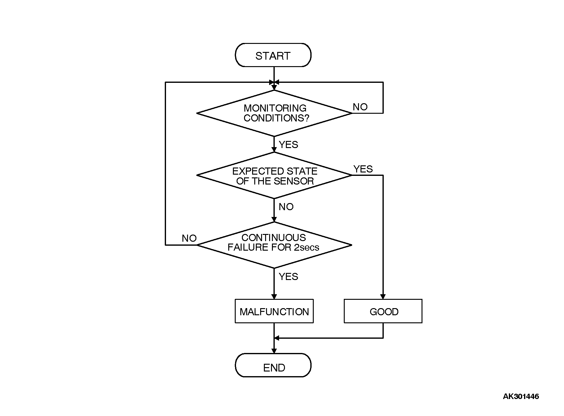
• Not applicable DTC SET CONDITIONS <Range/Performance problem - alignment> Logic Flow Chart
Check Conditions
Engine is being cranked.
Judgment Criteria
• Crankshaft position sensor output voltage has not changed (no pulse signal is input) for 2 seconds. DTC SET CONDITIONS <Circuit continuity> Logic Flow Chart
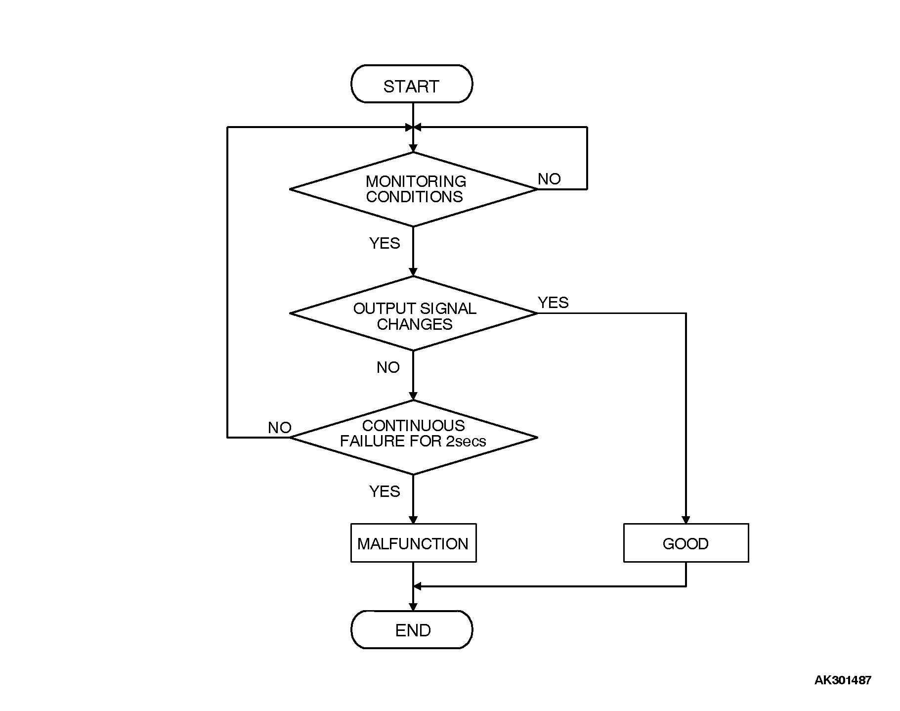
Check Conditions, Judgment Criteria
• Normal signal pattern has not been input for cylinder identification from the crankshaft position sensor signal and camshaft position sensor signal for 2 seconds. OBD-II DRIVE CYCLE PATTERN
Refer to Diagnostic Function - OBD-II Drive Cycle - Procedure 6 - Other Monitor . TROUBLESHOOTING HINTS (The most likely causes for this code to be set are:
• Crankshaft position sensor failed.
• Crankshaft sensing blade failed.
• Open or shorted crankshaft position sensor circuit, or harness damage or connector damage.
• PCM failed.
![[Previous]](../../../BUTTONS/fprev.png)
![[Next]](../../../BUTTONS/fnext.png)