DTC P0121: Throttle Position Sensor Circuit Range/Performance Problem
CIRCUIT OPERATION
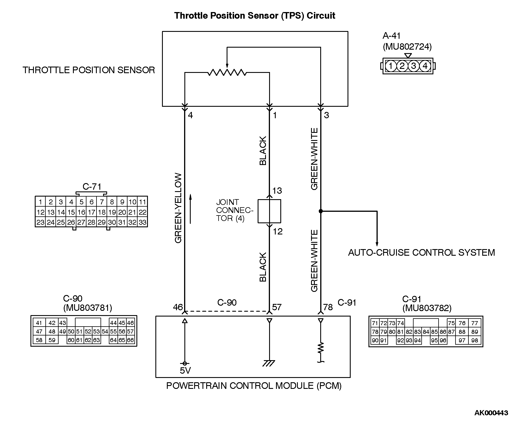
• A 5-volt power supply is applied on the TPS power terminal (terminal No. 4) from the PCM (terminal No. 46). The ground terminal (terminal No. 1) is grounded with PCM (terminal No. 57).
• When the throttle valve shaft is turned from the idle position to the fully opened position, the resistor between the TPS output terminal (terminal No. 3) and ground terminal will increase according to the rotation. TECHNICAL DESCRIPTION
• The TPS outputs voltage which corresponds to the throttle valve opening angle.
• The PCM checks whether the voltage is within a specified range. DESCRIPTIONS OF MONITOR METHODS
Compare load value with throttle position sensor output voltage. MONITOR EXECUTION
Continuous MONITOR EXECUTION CONDITIONS (Other monitor and Sensor)
Other Monitor (There is no temporary DTC stored in memory for the item monitored below)
• Not applicable
Sensor (The sensor below is determined to be normal)
• Volume airflow sensor DTC SET CONDITIONS <Range/Performance problem-low input> Logic Flow Chart
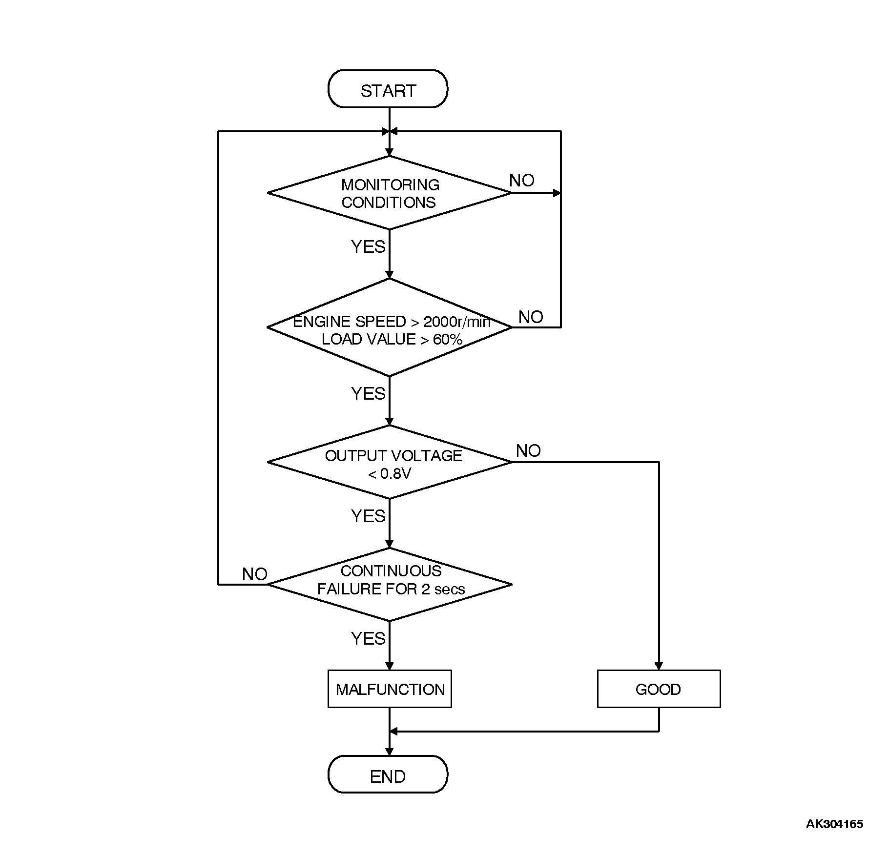
Check Conditions
2 seconds or more have passed since the staring sequence was completed.
Engine speed is higher than 2,000 r/min.
Volumetric efficiency is higher than 60 percent.
Judgement Criteria
• TPS output voltage has continued to be 0.8 volt or lower for 2 seconds. DTC SET CONDITIONS <Range/Performance problem-high input> Logic Flow Chart
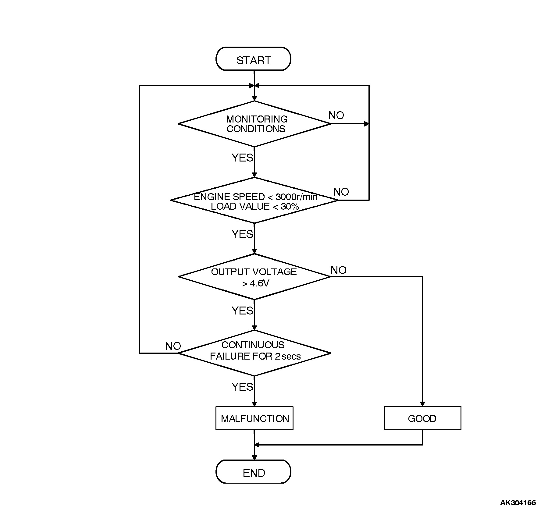
Check Conditions
2 seconds or more have passed since the staring sequence was completed.
Engine speed is lower than 3,000 r/min.
Volumetric efficiency is lower than 30 percent.
Judgement Criteria
• TPS output voltage has continued to be 4.6 volts or higher for 2 seconds. OBD-II DRIVE CYCLE PATTERN
Refer to Diagnostic Function - OBD-II Drive Cycle - Procedure 6 - Other Monitor . TROUBLESHOOTING HINTS (The most likely causes for this code to be set are:
• TPS failed or incorrectly adjusted.
• Open TPS circuit, harness damage or connector damage.
• PCM failed.
![[Previous]](../../../BUTTONS/fprev.png)
![[Next]](../../../BUTTONS/fnext.png)