DTC P0111: Intake Air Temperature Circuit Range/Performance Problem
CIRCUIT OPERATION
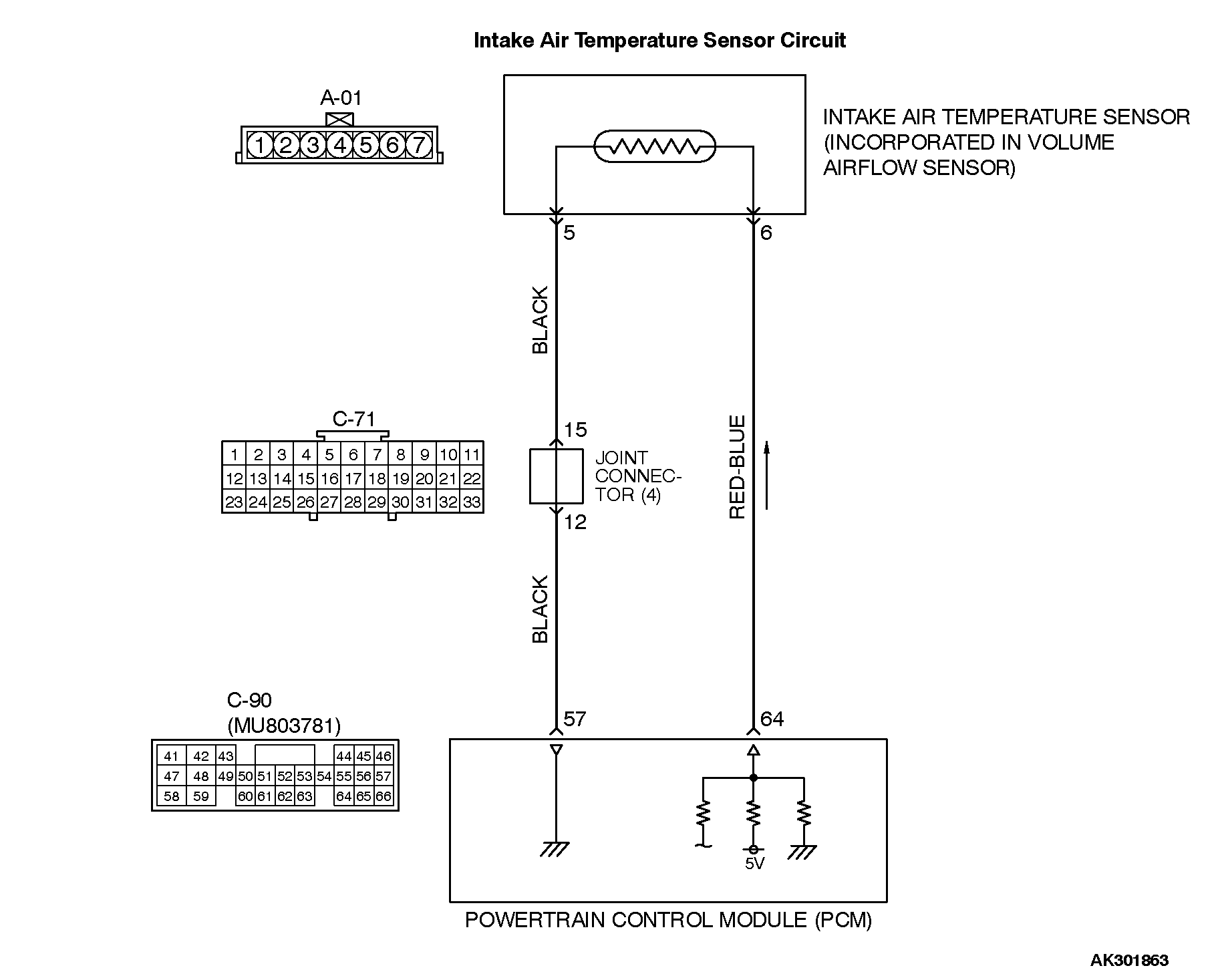
• Approximately 5 volts are applied to the intake air temperature sensor output terminal (terminal No. 6) from the PCM (terminal No. 64) via the resistor in the PCM. The ground terminal (terminal No. 5) is grounded with PCM (terminal No. 57).
• The intake air temperature sensor is a negative temperature coefficient type of resistor. When the intake air temperature rises, the resistance decreases.
• The intake air temperature sensor output voltage increases when the resistance increases and decreases when the resistance decreases. TECHNICAL DESCRIPTION
• The intake air temperature sensor converts the intake air temperature to a voltage.
• The PCM checks whether this voltage is within a specified range. DESCRIPTIONS OF MONITOR METHODS
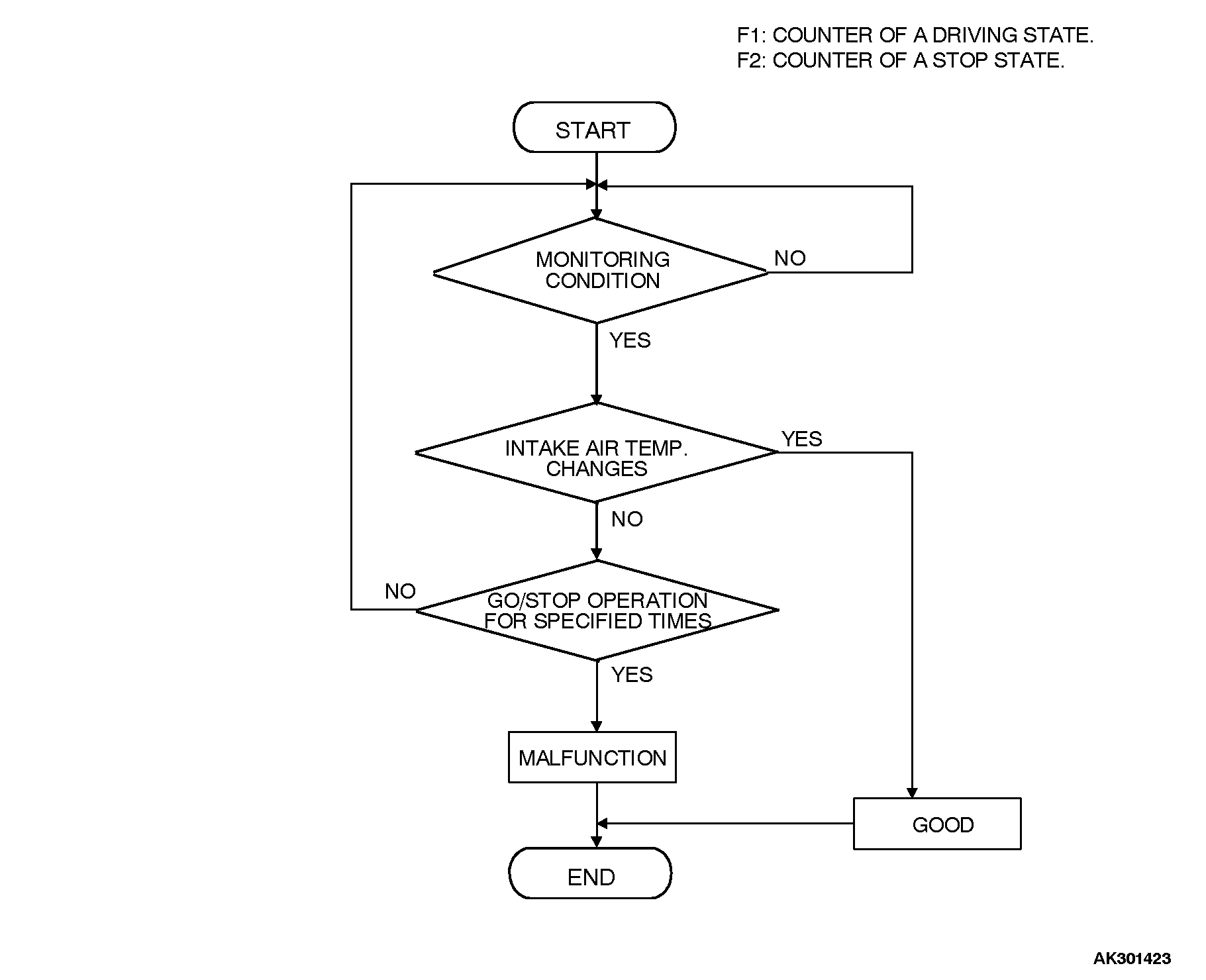
Intake air temperature sensor output voltage does not change when specified go/stop operations are repeated. MONITOR EXECUTION
Continuous MONITOR EXECUTION CONDITIONS (Other monitor and Sensor)
Other Monitor (There is no temporary DTC stored in memory for the item monitored below)
• Not applicable
Sensor (The sensor below is determined to be normal)
• Not applicable DTC SET CONDITIONS Logic Flow Chart
Check Conditions
Engine coolant temperature is higher than 76°C (169°F).
Repeat 5 or more times: drive*1, stop*2.
Drive*1: vehicle speed higher than 50 km/h (31 mph) lasting a total of more than 60 seconds.
Stop*2: vehicle speed lower than 1.5 km/h (0.9 mph) lasting more than 30 seconds.
Judgement Criteria
• Changes in the intake air temperature is lower than 1°C (1.8°F). OBD-II DRIVE CYCLE PATTERN
Refer to Diagnostic Function - OBD-II Drive Cycle - Procedure 6 - Other Monitor . TROUBLESHOOTING HINTS (The most likely causes for this code to be set are:
• Intake air temperature sensor failed.
• Harness damage in intake air temperature sensor circuit, or connector damage.
• PCM failed.
![[Previous]](../../../BUTTONS/fprev.png)
![[Next]](../../../BUTTONS/fnext.png)