DTC P0101: Volume Airflow Circuit Range / Performance Problem
CIRCUIT OPERATION
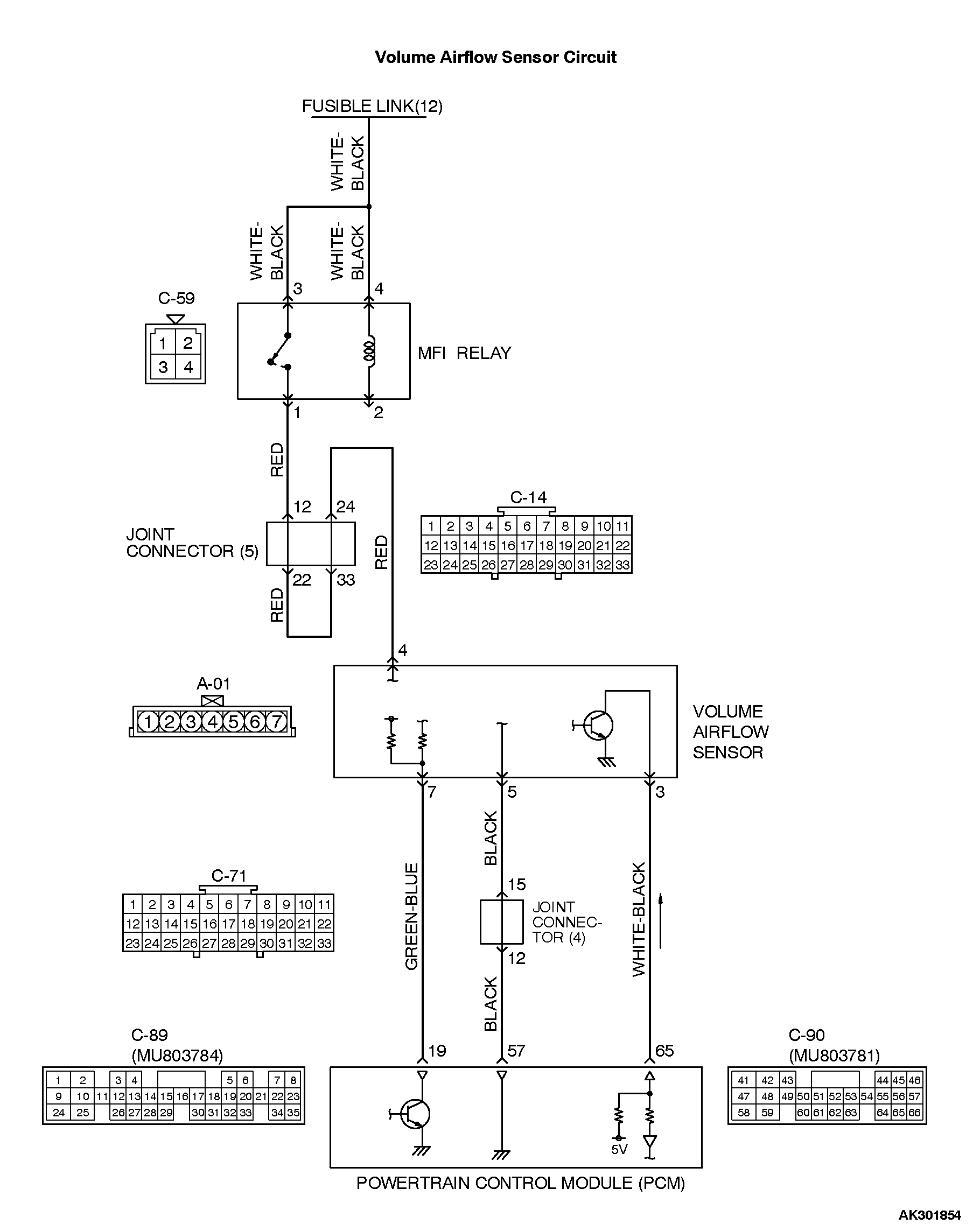
Ģ The volume airflow sensor power is supplied from the MFI relay (terminal No. 1), and the ground is provided on the PCM (terminal No. 57).
Ģ 5-volt power is applied to the volume airflow sensor output terminal (terminal No. 3) from the PCM (terminal No. 65). The volume airflow sensor generates a pulse signal when the output terminal and ground are opened/closed (opened/short).
Ģ 6-9volts power is applied to the PCM (terminal No.19) from the volume airflow sensor (terminal No.7).
Ģ The PCM (terminal No.19) controls the airflow sensor reset signal by turning the power transistor within the PCM to "ON" and "OFF" position. TECHNICAL DESCRIPTION
Ģ While the engine is running, the volume airflow sensor outputs a pulse signal which corresponds to the volume of air flow.
Ģ The PCM checks whether the frequency of this signal output by the volume airflow sensor while the engine is running is at or above the set value.
Ģ When the throttle position sensor output voltage is low, the PCM causes the power transistor to be "ON" to send an volume airflow sensor reset signal to the volume airflow sensor. In response to the reset signal, the volume airflow sensor resets the filter circuit and improves the ability of the airflow sensor to measure the amount of air in a small air intake region. DESCRIPTIONS OF MONITOR METHODS
Compare load value with volume airflow sensor output frequency. MONITOR EXECUTION
Continuous MONITOR EXECUTION CONDITIONS (Other monitor and Sensor)
Other Monitor (There is no temporary DTC stored in memory for the item monitored below)
Not applicable
Sensor (The sensor below is determined to be normal)
Throttle position sensor DTC SET CONDITIONS<Range/Performance-low input> Logic Flow Chart
Check Conditions
Throttle position sensor output voltage is 1.5 volts or higher.
Engine speed is higher than 2,000 r/min.
Judgement Criteria
Ģ Volume airflow sensor output frequency has continued to be 60 Hz or lower for 2 seconds. DTC SET CONDITIONS<Range/Performance-high input> Logic Flow Chart
Check Conditions
Throttle position sensor voltage is 2 volts or lower.
Engine speed is lower than 2,000 r/min.
Judgement Criteria
Ģ Volume airflow sensor output frequency has continued to be 800 Hz or higher for 2 seconds. OBD-II DRIVE CYCLE PATTERN
Refer to Diagnostic Function - OBD-II Drive Cycle - Procedure 6 - Other Monitor . TROUBLESHOOTING HINTS (The most likely causes for this code to be set are: )
Ģ Volume airflow sensor failed.
Ģ Open or shorted volume airflow sensor circuit, harness damage or connector damage.
Ģ PCM failed.
![[Previous]](../../../BUTTONS/fprev.png)
![[Next]](../../../BUTTONS/fnext.png)