CAN BUS DIAGNOSIS
<Up to 20 Model year>
Required Special Tools:
- MB992744: Vehicle communication interface-Lite (V.C.I.-Lite)
- MB992745: V.C.I.-Lite main harness A
- MB992747: V.C.I.-Lite USB cable short
- MB992748: V.C.I.-Lite USB cable long
| caution | Before connecting or disconnecting the scan tool (M.U.T.-IIISE), turn the ignition switch to the "LOCK" (OFF) position. |
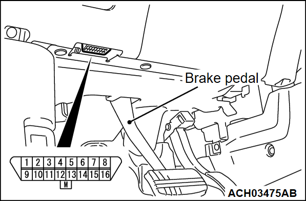
Connect the scan tool (M.U.T.-IIISE) to the 16-pin data link connector as follows.
| note | For details on how to use the scan tool (M.U.T.-IIISE), refer to the "M.U.T.-IIISE User's Manual." |
1. Start up the personal computer.
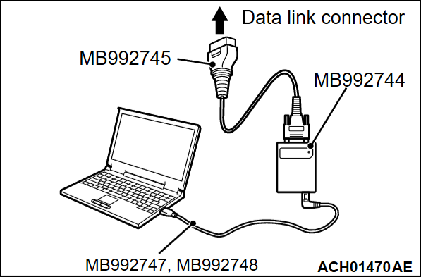
2. Connect special tool MB992747/MB992748 to special tool MB992744 and the personal computer.
3. Connect special tool MB992745 to special tool MB992744.
4. Connect special tool MB992745 to the data link connector of the vehicle.
| note | When special tool MB992744 is connected to the data link connector, special tool MB992744 indicator light will be illuminated in a green color. |
5. Start the scan tool (M.U.T.-IIISE) system on the personal computer and turn the ignition switch to the ON position.
6.
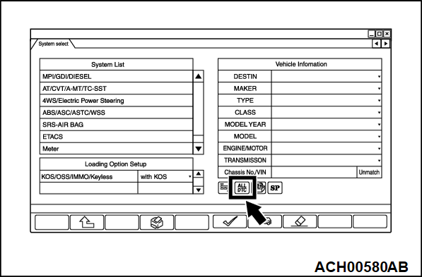
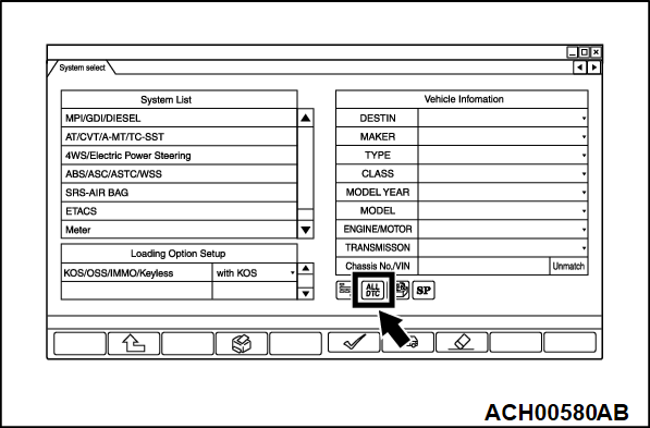
Press the "ALL DTC" icon on the "System Selection" screen.
| note | You cannot press the "ALL DTC" icon until all wearing options are selected. |
8.
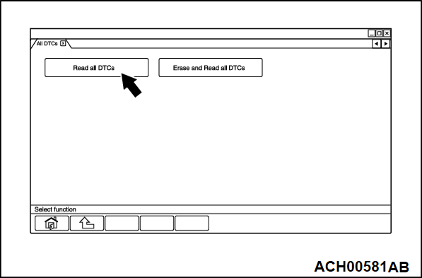
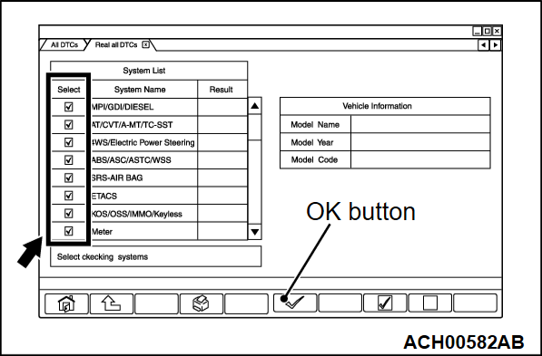
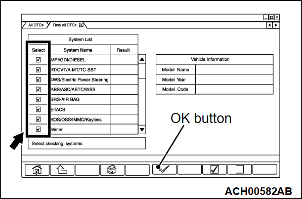
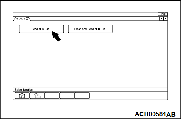
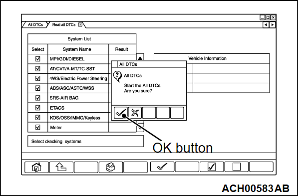
On the "Read all DTCs" screen, check whether the system installed in the vehicle is correctly selected in the check box on the left side of the screen (remove the check mark if necessary). If there is no problem in the selection, press the "OK" button.
| caution | If a check mark is displayed on a system that is not installed, be careful that you may judge incorrectly at the 10th item or later and spend unnecessary time in diagnosis. |
9.
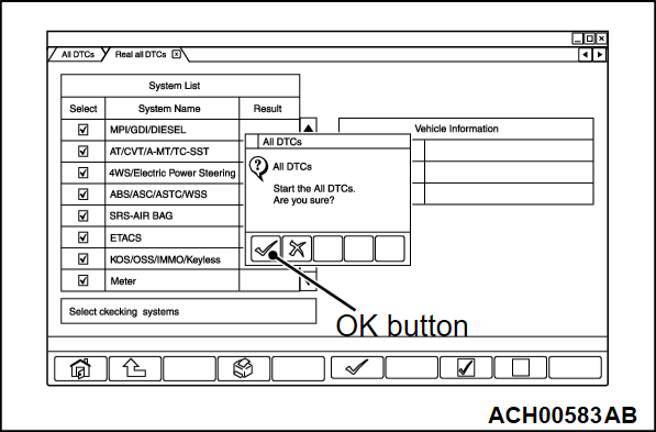
Since the execution confirmation screen of "Read all DTCs" is displayed, press the "OK" button to execute it.
10.
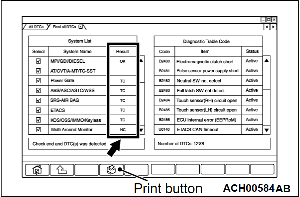
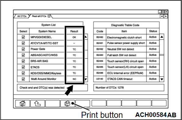
After completing the diagnosis reading of the system selected in the 9th item, judge whether there is an abnormality in the CAN bus line according to the contents displayed in the result field on the left side of the screen.
| note | The results can be printed with all diagnosis functions. |
11. If "NC" is displayed as a result after reading all diagnosis, check whether the system is installed in the vehicle. Remove the check mark on the selection screen if necessary. Then, read all diagnosis again.
<From 22 Model year>
Required Special Tools:
- MB992744: Vehicle communication interface-Lite (V.C.I.-Lite)
- MB992745: V.C.I.-Lite main harness A
- MB992747: V.C.I.-Lite USB cable short
- MB992748: V.C.I.-Lite USB cable long
| caution | Before connecting or disconnecting the scan tool (M.U.T.-IIISE), turn the ignition switch to the "LOCK" (OFF) position. |
Connect the scan tool (M.U.T.-IIISE) to the 16-pin data link connector as follows.
| note | For details on how to use the scan tool (M.U.T.-IIISE), refer to the "M.U.T.-IIISE User's Manual." |
1. Start up the personal computer.
2. Connect special tool V.C.I.-Lite USB cable (MB992747/MB992748) to V.C.I.-Lite (MB992744) and the personal computer.
3. Connect V.C.I.-Lite main harness A (MB992745)
to the V.C.I.-Lite.
4. Connect the V.C.I.-Lite main harness A to the data link connector of the vehicle.
| note | When the V.C.I.-Lite is connected to the data link connector, the V.C.I.-Lite indicator light will be illuminated in a green color. |
5. Start the scan tool (M.U.T.-IIISE) system on the personal computer and turn the ignition switch to the "ON" position.
6. On the "System Select" screen, select "Multi Channel Gateway" in the system list and then press the check icon.
| note | If the function selection screen is displayed, go back to "System Select" screen. If the communication error window is displayed, CAN-C (Diag) bus line has a malfunction. |
7.
Press the "ALL DTC" icon on the "System Selection" screen.
| note | You cannot press the "ALL DTC" icon until all wearing options are selected. |
9.
On the "Read all DTCs" screen, check whether the system installed in the vehicle is correctly selected in the check box on the left side of the screen (remove the check mark if necessary). If there is no problem in the selection, press the "OK" button.
| caution | If a check mark is displayed on a system that is not installed, be careful that you may judge incorrectly at the 10th item or later and spend unnecessary time in diagnosis. |
10.
Since the execution confirmation screen of "Read all DTCs" is displayed, press the "OK" button to execute it.
11.
After completing the diagnosis reading of the system selected in the 9th item, judge whether there is an abnormality in the CAN bus line according to the contents displayed in the result field on the left side of the screen.
| note | The results can be printed with all diagnosis functions. |
12. If "NC" is displayed as a result after reading all diagnosis, check whether the system is installed in the vehicle. Remove the check mark on the selection screen if necessary. Then, read all diagnosis again.
![[Previous]](../../../buttons/fprev.png)
![[Next]](../../../buttons/fnext.png)
