[Previous][Next]
REMOVAL AND INSTALLATION
 
 
<Up to 20 Model year>
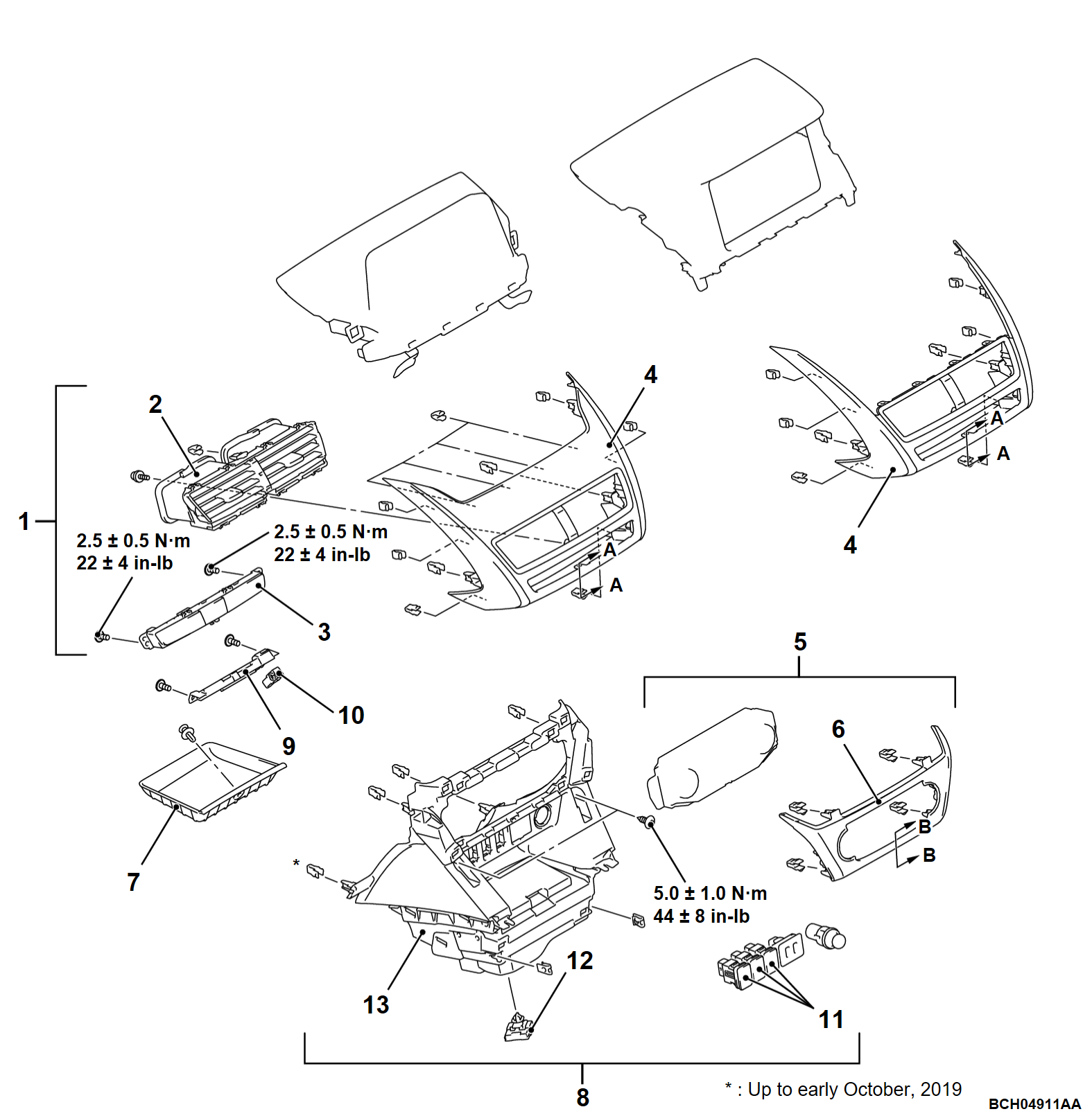
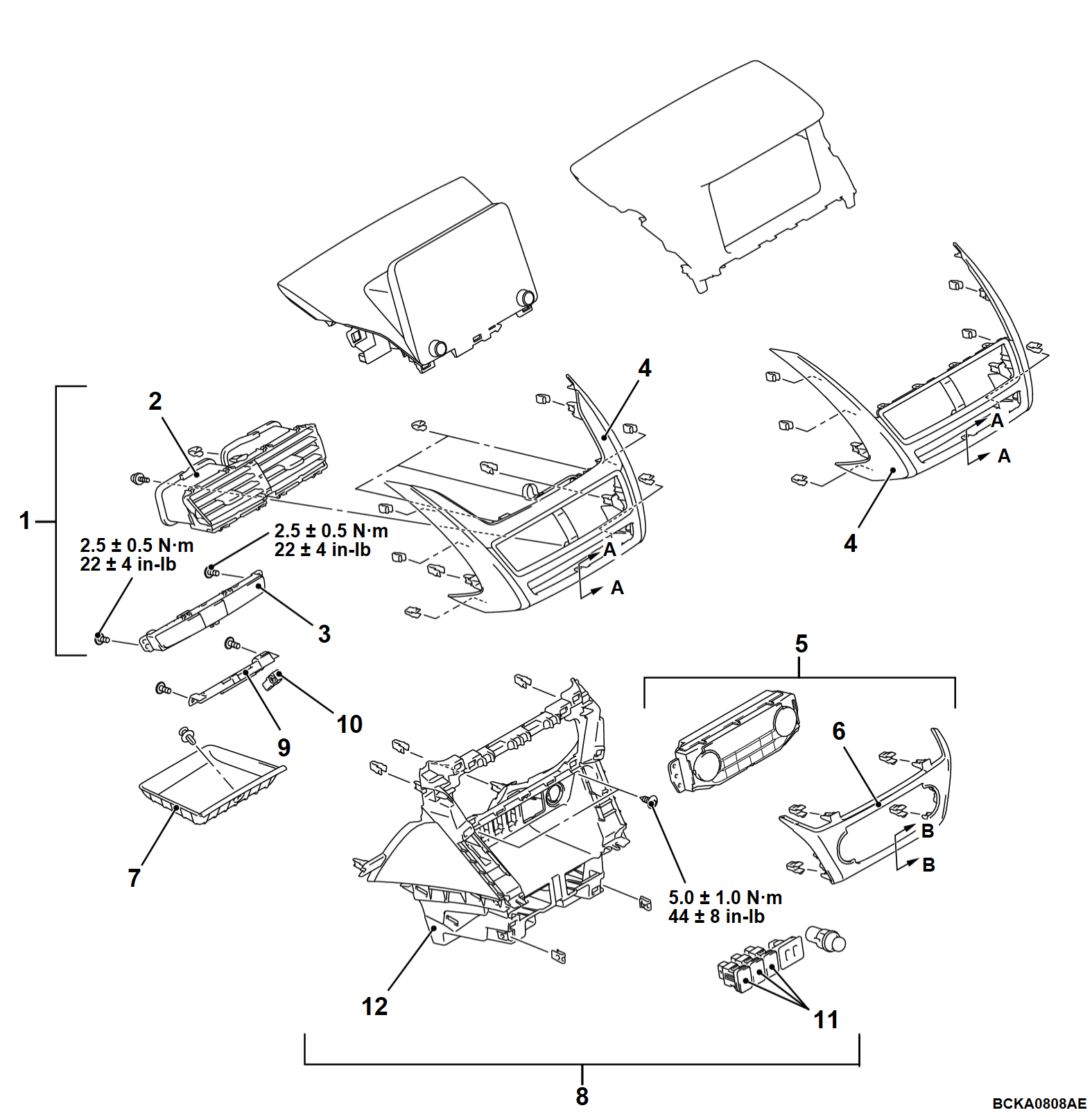
Removal steps
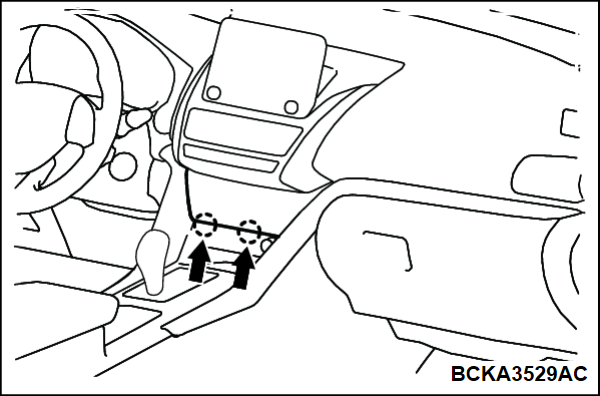
<<A>>1.Instrument panel air outlet panel assembly
2.Instrument panel air outlet center
3.Hazard warning light switch
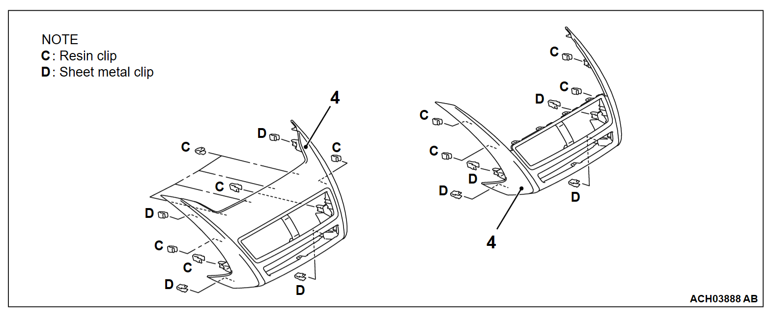
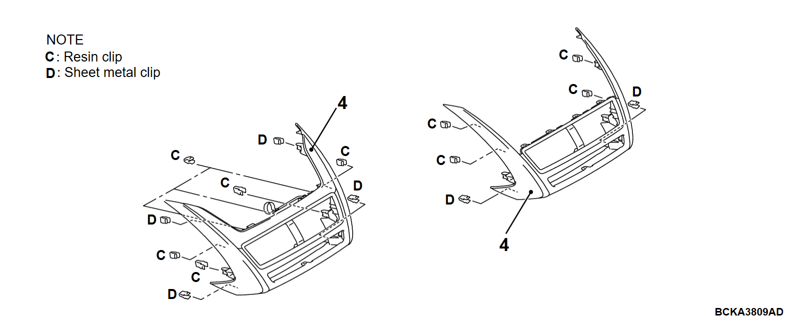
4.Instrument panel air outlet panel
Multivision display assembly (Refer to GROUP 54A - Multivision Display ) <Smartphone link display audio>.
Radio and CD player assembly (Refer to GROUP 54A - Radio and CD Player ) <Display audio>.
<<B>>5.A/C controller panel assembly
A/C controller assembly (Refer to GROUP 55 - A/C Control Unit ).
6.A/C controller panel
7.Instrument panel mat
Floor console center (Refer to ).
8.Instrument panel console box center assembly
ECALL relay box assembly (Refer to GROUP 54A - ECALL Relay Box Assembly ) <Vehicles with TCU>.
TCU (Refer to GROUP 54A - TCU ) <Vehicles with TCU>.
9.Instrument panel light assembly
10.Spotlight
11.Switch or switch plug
USB adapter or USB adapter plug (Refer to GROUP 54A - USB Cable ).
Accessory socket assembly (Refer to GROUP 54A - Accessory Socket ).
12.Jumper wiring harness <Vehicles without TCU>
13.Instrument panel console box center

Required Special Tool:
  • MB990784: Ornament Remover
 
 
REMOVAL SERVICE POINTS <Up to 20 Model year>
 
 
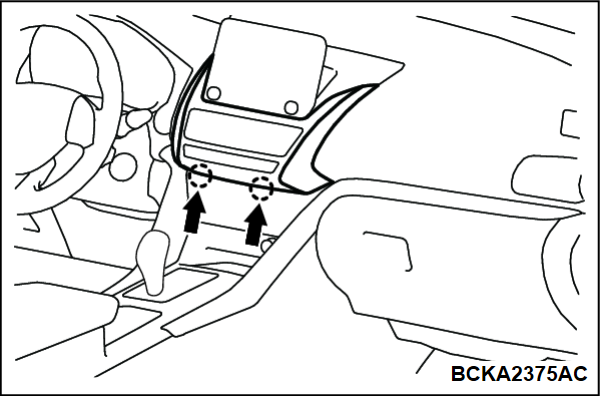
<<A>> INSTRUMENT PANEL AIR OUTLET PANEL ASSEMBLY REMOVAL
Insert the special tool MB990784 into each notch on the lower side of the instrument panel air outlet panel to remove it.


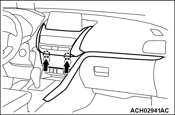
<<B>> A/C CONTROLLER PANEL ASSEMBLY REMOVAL
Insert the special tool MB990784 into each notch on the lower side of the A/C controller panel to remove it.


<From 22 Model year>
Removal steps
<<A>>>>B<<1.Instrument panel air outlet panel assembly
2.Instrument panel air outlet center
3.Hazard warning light switch
4.Instrument panel air outlet panel
Multivision display assembly (Refer to GROUP 54A - Multivision Display ).
<<B>>5.A/C controller panel assembly
A/C controller assembly (Refer to GROUP 55 - A/C Control Unit ).
6.A/C controller panel
7.Instrument panel mat
Glovebox case assembly (Refer to )
Floor console center (Refer to ).
8.Instrument panel console box center assembly
9.Instrument panel light assembly
10.Spot light
11.Switch or switch plug
USB adapter (Refer to GROUP 54A - USB Cable ).
Accessory socket assembly (Refer to GROUP 54A - Accessory Socket ).
12.Instrument panel console box center
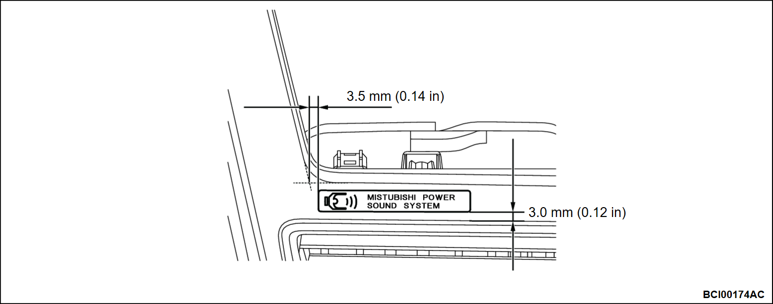
>>A<<13.Decal <Vehicles with audio amplifier>
 
 
REMOVAL SERVICE POINTS <From 22 Model year>
 
 
<<A>> INSTRUMENT PANEL AIR OUTLET PANEL ASSEMBLY REMOVAL
1. Insert the special tool ornament remover (MB990784) into each notch on the lower side of the instrument panel air outlet panel to remove it.
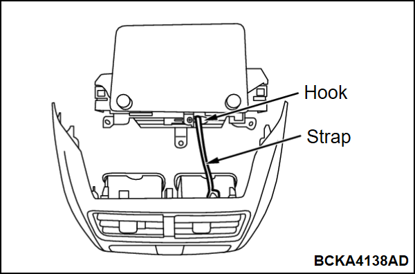
2. Remove the strap of instrument panel air outlet panel from the hook of multivision display.


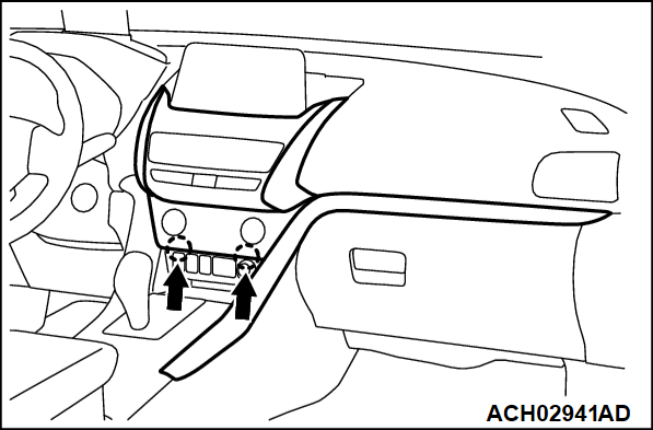
<<B>> A/C CONTROLLER PANEL ASSEMBLY REMOVAL
Insert the special tool ornament remover (MB990784) into each notch on the lower side of the A/C controller panel to remove it.


INSTALLATION SERVICE POINTS <From 22 Model year>
 
 
>>A<< DECAL APPLICATION
caution
  • When attaching the marks, the ambient temperature should be 20 - 38°C (68 - 100°F) and the air should be completely free of dust.
  • If the ambient temperature is lower than 20°C (68°F), the marks and the places on the vehicle body where the marks are to be attached should be heated to 20 - 30°C (68 - 86°F).
  • Soon after installing the marks, press them. Installation procedure.
1. Use Parts Cleaner (MZ100387 or equivalent) to clean the mark installation surfaces on the body.
2. Peel off the protection sheet on the back of the marks to paste it on the installation position.


>>B<< INSTRUMENT PANEL AIR OUTLET PANEL ASSEMBLY INSTALLATION
Install the strap of instrument panel air outlet panel to the hook of multivision display.