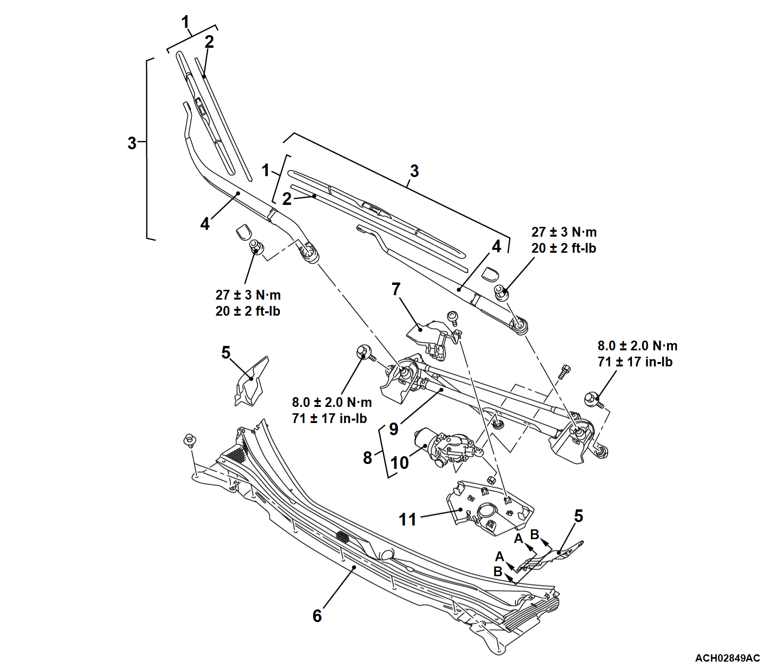
REMOVAL AND INSTALLATION
| note | For removal and installation of the wiper and washer switch, refer to GROUP 54A, Column Switch  . . |
REMOVAL SERVICE POINT
INSTALLATION SERVICE POINTS
>>A<< WINDSHIELD WIPER LINK ASSEMBLY INSTALLATION
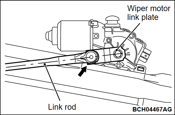
| caution | Always replace the wiper motor link plate with new one. |
2. Apply grease to the inside of link rod joint (as required) and connect the link rod to wiper motor link plate.
Specified grease: Multipurpose grease SAE J310, NLGI No.2 or equivalent
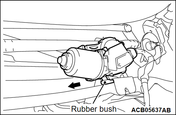
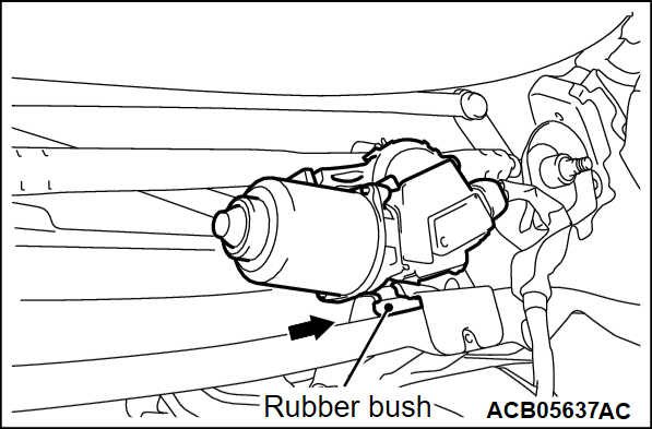
3. Make sure that the rubber bushing of the windshield wiper linkage assembly is secured in the windshield wiper bracket.
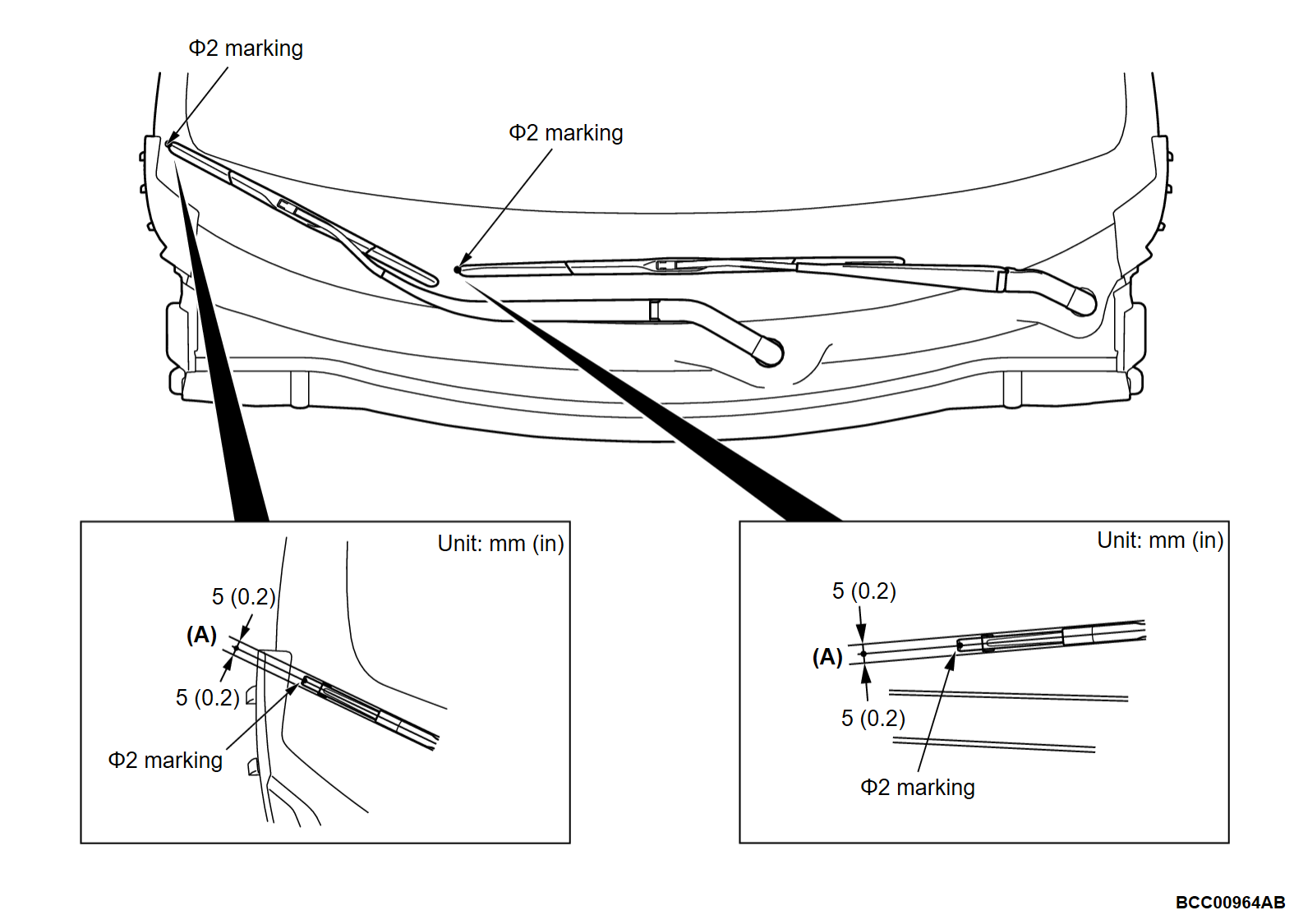
>>B<< WIPER ARM AND BLADE ASSEMBLY INSTALLATION
Install the wiper arm and blade assembly at the specified positions.
Standard value
(A): Φ 2 marking ± 5 mm (0.2 inch)
![[Previous]](../../../buttons/fprev.png)
![[Next]](../../../buttons/fnext.png)
