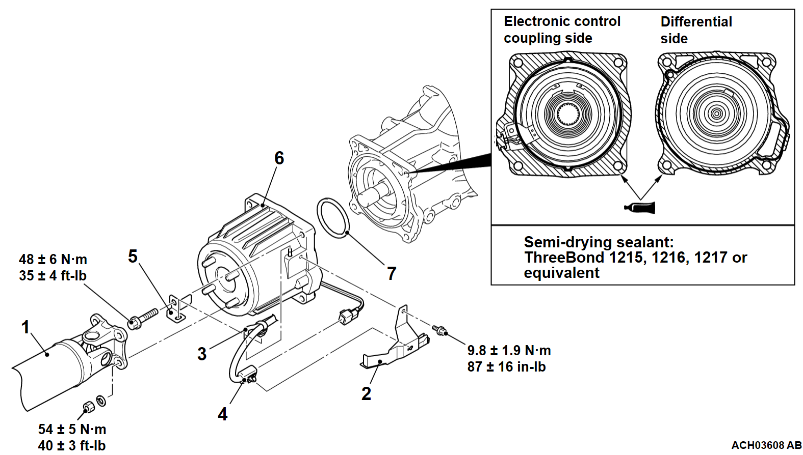
REMOVAL AND INSTALLATION
INSTALLATION SERVICE POINT
>>A<< ELECTRONIC CONTROL COUPLING INSTALLATION
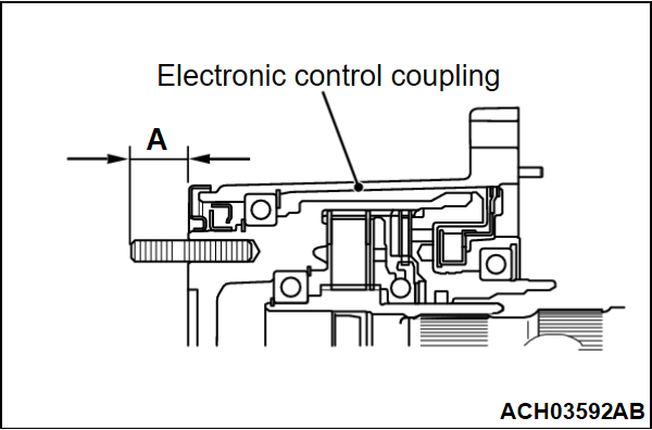
1. Check that the length of the electronic control coupling stud bolt (A) is within the standard value range.
Standard value: 22.3 - 25.1 mm (0.88 - 0.99 inch)
2. If it exceeds either of the limits, clean the threads for the electronic control coupling and replace the stud bolt.
Tightening torque: 15 ± 3 N·m (11 ± 2 ft-lb)
![[Previous]](../../../buttons/fprev.png)
![[Next]](../../../buttons/fnext.png)


