DIAGNOSTIC FUNCTION
WARNING INDICATOR
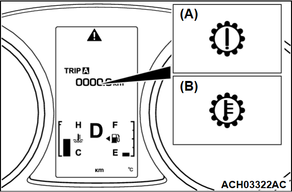
When any malfunction occurs in the items related to the CVT system, which are described below, the symbol (A) continues being displayed in the information screen in the multi information display.
Check if the diagnostic trouble code is set when the symbol (A) continues being displayed in the information screen in the multi information display.
| note | When the symbol (B) is displayed in the information screen in the multi information display, the transmission fluid temperature is high. (Symbol (B) is turned on when the fluid temperature is approximately 138°C (280°F) or higher and turned off automatically when the fluid temperature drops below approximately 135°C (275°F).) |
ON-BOARD DIAGNOSTICS
The transaxle control module (TCM) monitors its input/output signals (some signals all the time and others under specified conditions). When an irregular signal is initially monitored, the TCM decides that a malfunction has occurred and records the occurrence as a diagnostic trouble code. There are 43 diagnostic items. The diagnostic results can be read with scan tool. Diagnostic trouble codes are kept in memory by direct battery feed. The codes are retained in memory even if the ignition switch is in the "LOCK" (OFF) position. DTCs are not erased even after the battery terminals and the TCM connector are disconnected. In addition, the diagnostic trouble code can also be erased by scan tool.
| note | If a sensor is disconnected when the ignition switch is in the "ON" position, a diagnostic trouble code is stored in memory. In this case, erase the DTC using scan tool. |
The 43 diagnostic items are displayed in numeric order.
HOW TO CONNECT THE SCAN TOOL (M.U.T.-III)
Required Special Tools:
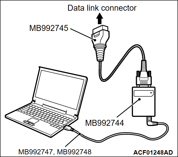
- MB992744: Vehicle communication interface-Lite (V.C.I.-Lite)
- MB992745: V.C.I.-Lite main harness A
- MB992747: V.C.I.-Lite USB cable short
- MB992748: V.C.I.-Lite USB cable long
1.
| caution | To prevent damage to scan tool (M.U.T.-IIISE), always turn the ignition switch to the "LOCK" (OFF) position before connecting or disconnecting scan tool (M.U.T.-IIISE). |
Ensure that the ignition switch is at the "LOCK" (OFF) position.
2. Start up the personal computer.
3. Connect special tool MB992747/M992748 to special tool MB992744 and the personal computer.
4. Connect special tool MB992745 to special tool MB992744.
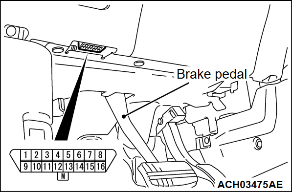
5. Connect special tool MB992745 to the data link connector.
| note | When the special tool MB992745 is connected to the data link connector, the special tool MB992744 indicator light will be illuminated in a green color. |
6. Start the M.U.T.-IIISE system on the personal computer.
| note | Disconnecting scan tool (M.U.T.-IIISE) is the reverse of the connecting sequence, making sure that the ignition switch is at the "LOCK" (OFF) position. |
HOW TO READ AND ERASE DIAGNOSTIC TROUBLE CODES
Required Special Tools:
- MB992744: Vehicle communication interface-Lite (V.C.I.-Lite)
- MB992745: V.C.I.-Lite main harness A
- MB992747: V.C.I.-Lite USB cable short
- MB992748: V.C.I.-Lite USB cable long
| caution | <From 19 Model year>
|
1.
| note | If the battery voltage is low, diagnostic trouble codes will not be set. Check the battery if scan tool (M.U.T.-IIISE) does not display. |
Connect scan tool (M.U.T.-IIISE) to the data link connector.
2. Turn the ignition switch to the "ON" position.
3. Select "STV."
4. Select "AT/CVT/A-MT/TC-SST."
5. Select "Diagnostic Trouble Code" to read the DTC.
6. If a DTC is set, it is shown.
7. Choose "Erase DTCs" to erase the DTC.
HOW TO READ DATA LIST
Required Special Tools:
- MB992744: Vehicle communication interface-Lite (V.C.I.-Lite)
- MB992745: V.C.I.-Lite main harness A
- MB992747: V.C.I.-Lite USB cable short
- MB992748: V.C.I.-Lite USB cable long
1. Connect scan tool (M.U.T.-IIISE) to the data link connector.
2. Turn the ignition switch to the "ON" position.
3. Select "STV."
4. Select "AT/CVT/A-MT/TC-SST."
5. Select "Data List."
6. Choose an appropriate item and select the "OK" button.
HOW TO DIAGNOSE THE CAN BUS LINES
Required Special Tools:
- MB992744: Vehicle communication interface-Lite (V.C.I.-Lite)
- MB992745: V.C.I.-Lite main harness A
- MB992747: V.C.I.-Lite USB cable short
- MB992748: V.C.I.-Lite USB cable long
1. Connect scan tool (M.U.T.-IIISE) to the data link connector.
2. Turn the ignition switch to the "ON" position.
3. Select "CAN bus diagnosis" from the start-up screen.
4. When the optional equipment screen is displayed, choose the one which the vehicle is fitted with, and then select the "OK" button.
![[Previous]](../../../buttons/fprev.png)
![[Next]](../../../buttons/fnext.png)


