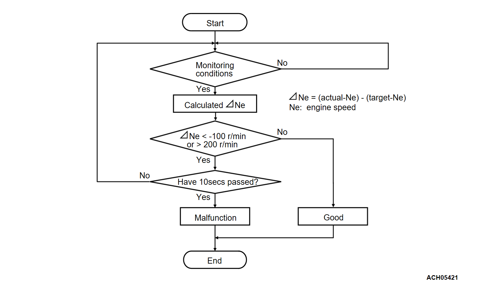
DTC P050A: Cold Start Idle Air Control System Performance
TECHNICAL DESCRIPTION
- The amount of air taken in during idling is regulated by the opening and closing of the throttle valve.
- The ECM checks the difference between the actual engine speed and the target engine speed.
DESCRIPTIONS OF MONITOR METHODS
Difference between actual and target idle speed is over the specified value.
MONITOR EXECUTION
- Continuous
MONITOR EXECUTION CONDITIONS (Other monitor and Sensor)
Other Monitor (There is no temporary DTC set in memory for the item monitored below)
- Misfire monitor
- Fuel system monitor
Sensor (The sensor below is determined to be normal)
- Mass airflow sensor
- Engine coolant temperature sensor
- Intake air temperature sensor 1
- Barometric pressure sensor
- Throttle position sensor
Check Conditions
- Under the closed loop idle speed control.
- The engine coolant temperature is between 7°C (45°F) and 50°C (122°F).
- Battery positive voltage is higher than 10 volts.
- Barometric pressure is higher than 76 kPa (22.4 in.Hg).
- Intake air temperature is higher than -10°C (14°F).
- More than 3 seconds have elapsed from the previous monitoring.
Judgment Criterion
- The actual idle speed is less than -100 r/min lower than the target idle speed for 10 seconds.
Check Conditions
- Under the closed loop idle speed control.
- The engine coolant temperature is between 7°C (45°F) and 50°C (122°F).
- Battery positive voltage is higher than 10 volts.
- Barometric pressure is higher than 76 kPa (22.4 in.Hg).
- Intake air temperature is higher than -10°C (14°F).
- More than 3 seconds have elapsed from the previous monitoring.
Judgment Criterion
- Actual idle speed has continued to be higher than the target idle speed by 200 r/min or more for 10 seconds.
FAIL-SAFE AND BACKUP FUNCTION
- None.
TROUBLESHOOTING HINTS (The most likely causes for this code to be set are:)
- Throttle valve area is dirty.
- Throttle body assembly failed.
- ECM failed.
DIAGNOSIS
STEP 1. Using scan tool (M.U.T.-IIISE), read the diagnostic trouble code (DTC).
| caution | To prevent damage to scan tool (M.U.T.-IIISE), always turn the ignition switch to the "LOCK" (OFF) position before connecting or disconnecting scan tool (M.U.T.-IIISE). |
(2) Turn the ignition switch to the "ON" position.
(3) Read the DTC again.
(4) Turn the ignition switch to the "LOCK" (OFF) position.
Is the diagnostic trouble code other than P050A set?
STEP 2. Check the intake system vacuum leak.
STEP 3. Check the throttle body. (throttle valve area)
Is the throttle valve area dirty?
![[Previous]](../../../buttons/fprev.png)
![[Next]](../../../buttons/fnext.png)


