IGNITION TIMING CHECK
Required Special Tools:
- MB992744: Vehicle communication interface-Lite (V.C.I.-Lite)
- MB992745: V.C.I.-Lite main harness A
- MB992747: V.C.I.-Lite USB cable short
- MB992748: V.C.I.-Lite USB cable long
1. Before inspection, set the vehicle to the pre-inspection condition.
2. Turn the ignition switch to the "LOCK" (OFF) position and then connect the scan tool (M.U.T.-IIISE) to the data link connector [Refer to GROUP 13A - Direct Fuel Injection and Multiport Fuel Injection (DFI and MFI) Diagnosis, Diagnostic Function  ].
].
 ].
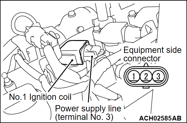
].3. Set the timing light to the power supply line (terminal No. 3) of the ignition coil No. 1.
4. Start the engine and let it run at idle.
5. Select the item No. 2 on scan tool (M.U.T.-IIISE) and measure engine idle speed and check that it is approximately 750 r/min.
6. Select No. 11 (actuator test function) of the scan tool (M.U.T.-IIISE), and set the ignition timing to the basic ignition timing.
7. Check that basic ignition timing is within the standard value.
Standard value: 5° BTDC ± 3°
8. If the basic ignition timing is not within the standard value [Refer to GROUP 13A - Direct Fuel Injection and Multiport Fuel Injection (DFI and MFI) Diagnosis, Symptom Chart  ].
].
 ].
].| caution | If the test is not cancelled, a forced driving will continue for 27 minutes. Driving under this condition may damage the engine. |
9. Cancel the actuator test function item No. 11, Basic ignition timing set mode, on scan tool (M.U.T.-IIISE).
10. Check that ignition timing is at the standard value.
Standard value: approximately 10° BTDC
| note |
|
11. Remove the timing light.
12. Turn the ignition switch to the "LOCK" (OFF) position and then disconnect the scan tool (M.U.T.-IIISE).
![[Previous]](../../../buttons/fprev.png)
![[Next]](../../../buttons/fnext.png)
