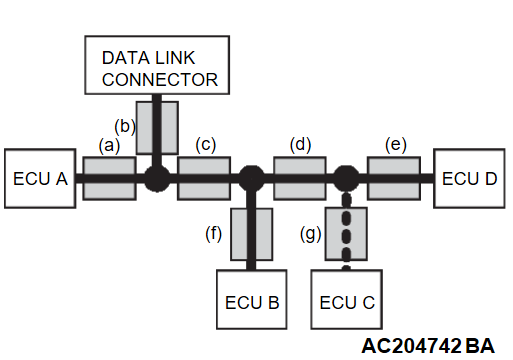
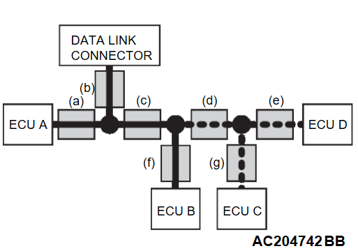
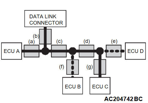
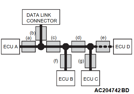
EXPLANATION ABOUT THE SCAN TOOL (M.U.T.-IIISE) CAN BUS DIAGNOSTICS
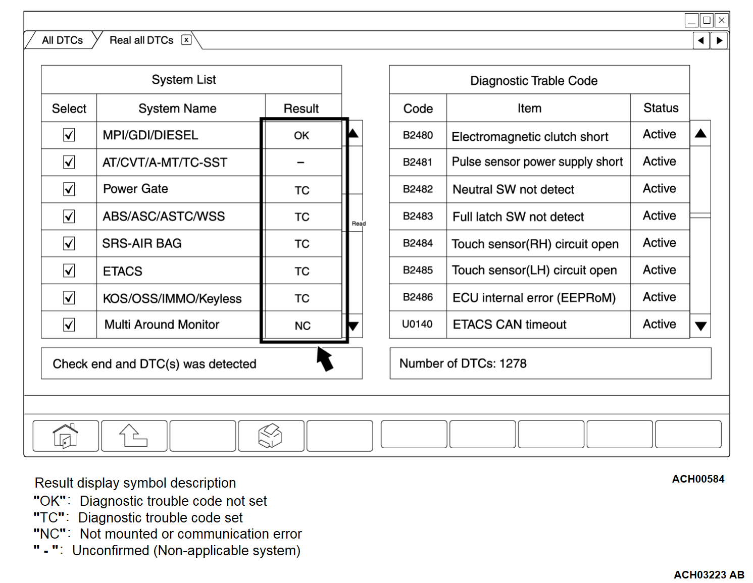
The CAN bus is diagnosed by using "Read all DTCs" function on the scan tool (M.U.T.-IIISE). "Read all DTCs" automatically reads the diagnostic trouble code from all the ECUs selected in the system list, and displays the diagnostic results in the result field on the left side of the screen and the status of the diagnostic trouble code on the right side of the screen as the respective results. In the CAN bus diagnostics using "Read all DTCs" of the scan tool (M.U.T.-IIISE), it is judged whether there is an abnormality in the CAN bus line based on the diagnostic results displayed in the result field on the left side of the screen.
| Screen image of the scan tool (M.U.T.-IIISE) (Read all DTCs) | Result field (Left side of the screen) | Action |
| "OK" or "-" is displayed for all the systems. | Perform normal failure phenomenon diagnosis. | |
| "TC" is displayed for one or more systems and "NC" is not displayed at all. | After reading the diagnostic trouble code, pinpoint the trouble spot according to the diagnostic trouble code or perform normal failure phenomenon diagnosis. | |
| "NC" is displayed for one or more systems. | Write down all the systems for which "NC" is displayed, and proceed to CAN Bus Diagnostics Table. |
CAN BUS LINE DIAGNOSTIC FLOW
1. The scan tool (M.U.T.-IIISE) CAN bus diagnostics
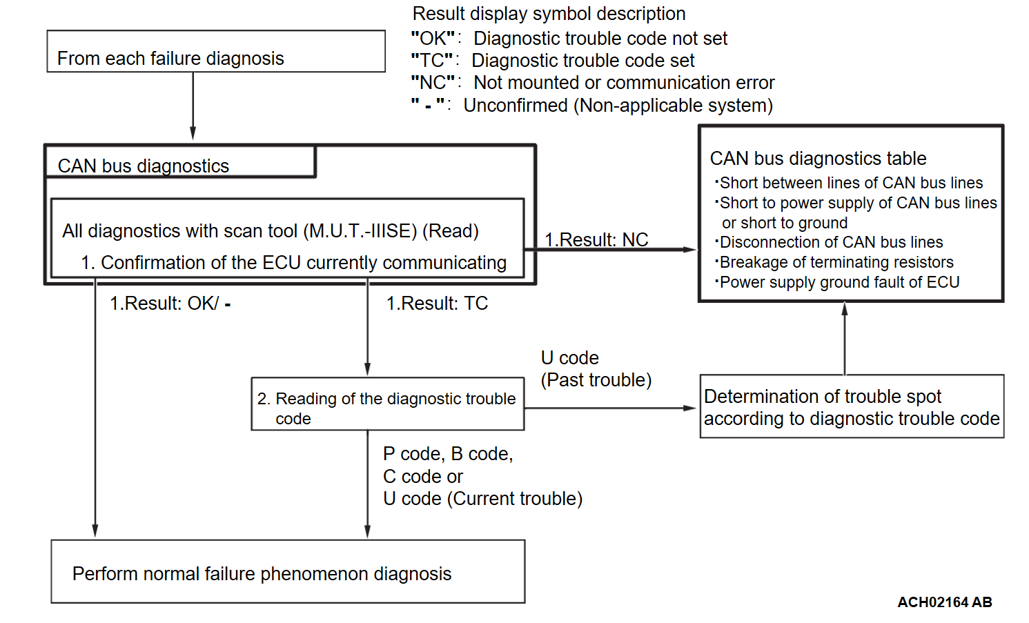
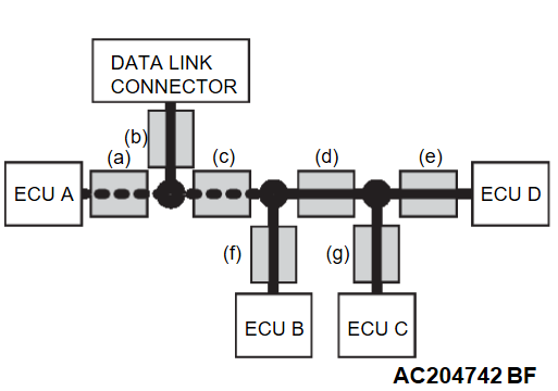
The scan tool (M.U.T.-IIISE) diagnoses CAN bus lines in accordance with the following strategy.
- Checking the communication condition of ECUsThe scan tool (M.U.T.-IIISE) narrows down troubles in circuit by itself. Its strategies are as follows.
| ECU which cannot communicate with the scan tool (M.U.T.-IIISE) | Possible trouble spot | Logic for narrowing down trouble spot | |
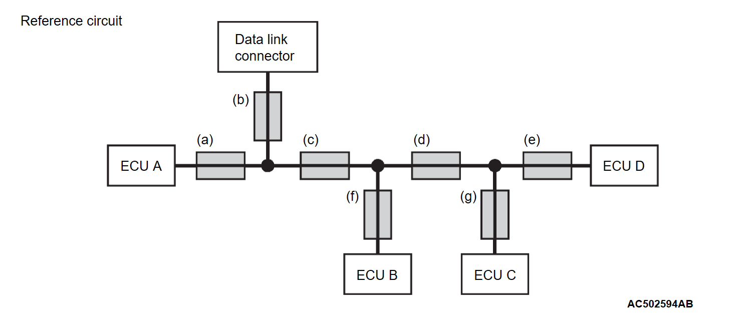
| ECU A | CAN bus line (a) and power supply system to ECU A | ECU A communicates with the scan tool (M.U.T.-IIISE) via CAN bus lines (a) and (b). The scan tool (M.U.T.-IIISE) judges that CAN bus line (b) is normal, because it can communicate with other ECUs. Possible trouble may be present in CAN bus line (a) or the power supply system to ECU A. | |
| ECU C | CAN bus line (g) and power supply system to ECU C | ECU C communicates with the scan tool (M.U.T.-IIISE) via CAN bus lines (b), (c), (d) and (g). The scan tool (M.U.T.-IIISE) judges that CAN bus lines (b), (c) and (d) are normal, because it can communicate with ECUs B and D. Possible trouble may be present in CAN bus line (g) or the power supply system to ECU C. | |
| ECU C and ECU D | Trouble in CAN bus line (d) | ECUs C ad D communicate with the scan tool (M.U.T.-IIISE) via CAN bus lines (b), (c), (d), (e) and (g). The scan tool (M.U.T.-IIISE) judges that CAN bus lines (b) and (c) are normal, because it can communicate with ECU B. Possible trouble may be present in CAN bus line (d), (e) or (g) or the power supply system to ECU D or C. CAN bus line (d) is shared by ECUs C and D when they communicate with the scan tool (M.U.T.-IIISE), so CAN bus line (d) is suspected as ultimate cause. CAN bus line (g) or (e) and power supply systems to ECU C or D are also suspected as second cause. | |
| ECU B and ECU D | CAN bus line (e) or (f) or power supply system to ECU B or D | ECUs B ad D communicate with the scan tool (M.U.T.-IIISE) via CAN bus lines (b), (c), (d), (e) and (f). The scan tool (M.U.T.-IIISE) judges that CAN bus lines (b), (c) and (d) are normal, because it can communicate with ECU C. Possible trouble may be present in CAN bus line (f) or (e) or the power supply system to ECU B or D. | |
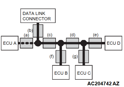
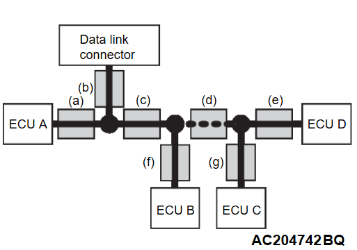
2. If diagnostic trouble code related to CAN communication is set as past trouble, isolate opens as described below.
| note | If you pinpoint trouble spot according to diagnostic trouble code, you should use time-out diagnostic trouble code. diagnostic trouble code related to failure information is set when the data to be set contains an error, so CAN bus line itself is probably normal. |
| note | Time-out diagnostic trouble codes are stored in each ECU memory individually. Therefore, it is possible that these diagnostic trouble codes have not been set simultaneously. If the trouble spot cannot be found when you diagnose by judging from multiple diagnostic trouble codes, check the communication lines between each ECU. |
| Diagnostic trouble code to be set | Possible trouble spot | Logic for narrowing down trouble spot | |
| Time-out diagnostic trouble code associated with ECU D is set in ECU A, ECU B and ECU C. | Trouble in CAN bus line (e) and power supply system to ECU D | When time-out diagnostic trouble code associated with ECU D is set in ECU A, B and C, or time-out diagnostic trouble code associated with ECUs A, B and C is set in ECU D, CAN bus line (e) is suspected. When diagnostic trouble code is not set in ECU D, the power supply to ECU D is suspected. | |
| Time-out diagnostic trouble code associated with ECUs A, B, C and D is set in ECU. | |||
| Time-out diagnostic trouble code associated with ECU A is set in ECUs B, C and D. | Trouble in CAN bus line (a) or (c) and power supply system to ECU A. | When time-out diagnostic trouble code associated with ECU A is set in ECUs B, C and D, or time-out diagnostic trouble code associated with ECUs B, C and D is set in ECU A, CAN bus line (a) or (c) is suspected. When diagnostic trouble code is not set in ECU A, the power supply to ECU A is suspected. | |
| Time-out diagnostic trouble code associated with ECUs B, C and D is set in ECU A. | |||
| Time-out diagnostic trouble codes associated with ECUs C and D are set in ECU A and ECU B. | Trouble in CAN bus line (d) | If time-out diagnostic trouble codes associated with ECUs C and D are set in ECUs A and B, or time-out codes associated with ECUs A and B are set in ECUs C and D, CAN bus line (d) is suspected. CAN bus line (g) or (e) and power supply systems to ECU C or D are also suspected as second cause. | |
| Time-out diagnostic trouble codes associated with ECUs A and B are set in ECU C and ECU D. | |||
![[Previous]](../../../buttons/fprev.png)
![[Next]](../../../buttons/fnext.png)
