DTC B1762 IOD fuse not seated fully
| caution |
|
TROUBLE JUDGMENT
- When voltage at the power supply fuse (No.22) drops below 5 volts with the ignition switch "ON" and then the ACC OFF signal is detected for 5 seconds, the ETACS-ECU will set DTC B1762.
TROUBLESHOOTING HINTS
- The fuse No. 22 may be defective
- The ETACS-ECU may be defective
- The KOS&OSS-ECU may be defective <Vehicles with KOS>
- The wiring harness or connectors may have loose, corroded, or damaged terminals, or terminals pushed back in the connector
DIAGNOSIS
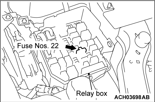
STEP 1. Check the power supply fuses (No.22).
Check the power supply fuses (No.22) (Refer to GROUP 00 - How to Use Troubleshooting/Inspection Service Points - Inspection Service Points for a Blown Fuse  ).
).
 ).
).Is the fuse in good condition?
STEP 2. Check of short to power supply, short to ground, and open circuit in IODI line between fusible link and ETACS-ECU connector.
Is the check result normal?
STEP 3. Using scan tool (M.U.T.-IIISE), read the other DTC.
(1)
| caution | To prevent damage to scan tool (M.U.T.-IIISE), always turn the ignition switch to the "LOCK" (OFF) position before connecting or disconnecting scan tool (M.U.T.-IIISE). |
(2) Turn the ignition switch to the "ON" position.
(3) Check whether the KOS&OSS-ECU related DTC is set.
(4) Turn the ignition switch to the "LOCK" (OFF) position.
Is the DTC set?
STEP 4. Check of short to power supply, short to ground, and open circuit in ACC line between ignition switch (ACC) <Vehicles without KOS> or KOS&OSS-ECU (ACC) <Vehicles with KOS> and ETACS-ECU connector.
Is the check result normal?
STEP 5. Using scan tool (M.U.T.-IIISE), read the DTC again.
Check again if the DTC is set in the ETACS-ECU. Replace the ETACS-ECU.
(1) Erase the DTC.
(2) Turn the ignition switch from "LOCK" (OFF) position to "ON" position.
(3) Check if DTC is set.
Is the DTC set?
 Replace the ETACS-ECU.
![[Previous]](../../../buttons/fprev.png)
![[Next]](../../../buttons/fnext.png)

