DIAGNOSIS MODE
HOW TO INITIATE THE DIAGNOSIS MODE
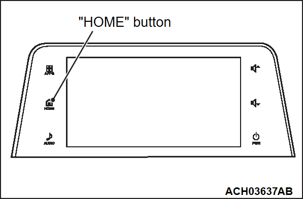
1. Press "HOME" button while the multivision display is ON.
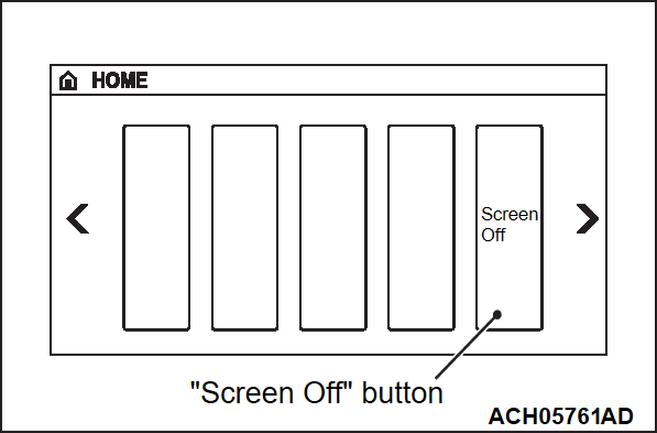
2. Select "Screen Off" button on "Home" screen.
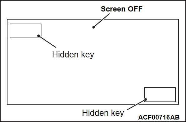
3. "Screen OFF" screen will be displayed.
4. Press and hold the hidden key at the left upper corner on the "Screen OFF" screen for three seconds. Then press the hidden key at the right lower corner briefly.
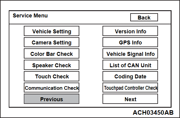
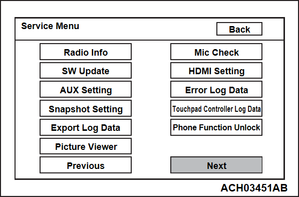
5. The "Service Menu" screen, i.e. top screen of the diagnosis mode is displayed.
HOW TO TERMINATE THE DIAGNOSIS MODE
When you perform the operation below, the service mode will terminate and the "Home" screen will be displayed.
- You press the "Back" button while the "Service Menu" screen is displayed.
SERVICE MODE ITEM
You can select a required screen by pressing a corresponding button on the "Service Menu" screen.
- Vehicle Setting
- AUX Setting
- Touch Check
- Version Info
- Communication Check
- Vehicle Signal Info
- Color Bar Check
- Speaker Check
- GPS Info
- List of CAN Unit
- Coding Data
- Camera Setting <Vehicles without multi around monitor>
- Radio Info
- Snapshot Setting
- SW Update
- Export Log Data
- Picture Viewer
- Mic Check
- HDMI Setting
- Error Log Data
- Touchpad Controller Check
- Touchpad Controller Log Data
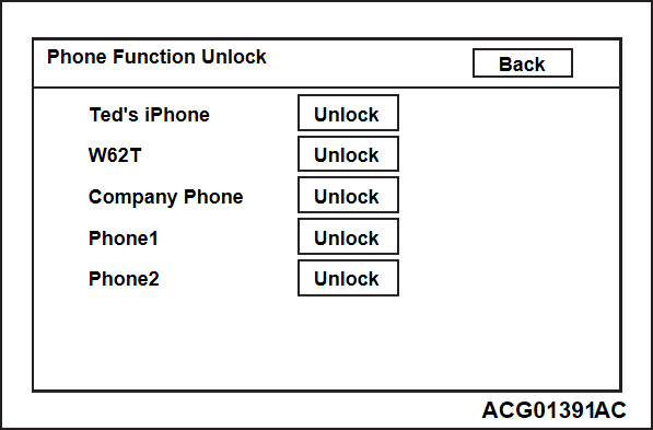
- Phone Function Unlock
Vehicle Setting
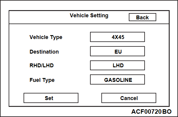
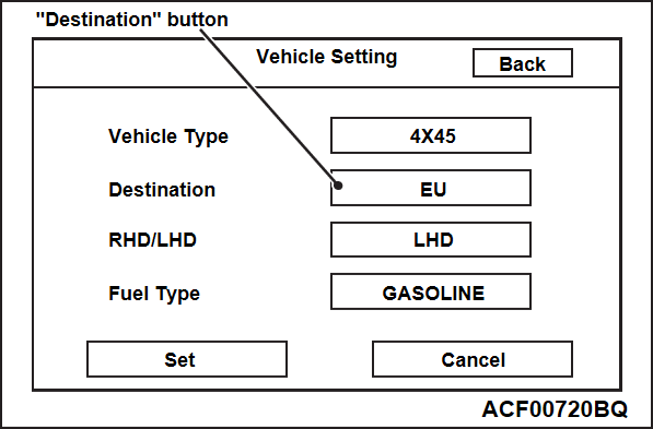
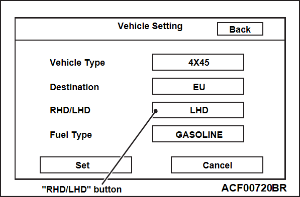
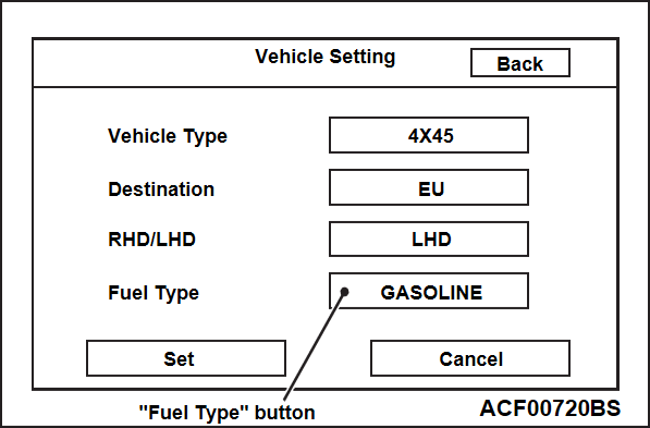
"Vehicle Setting" screen will be displayed by selecting "Vehicle Setting" button on "Service Menu" screen. The following settings can be made on "Vehicle Setting" screen.
- Vehicle Type Setting
- Destination Setting
- Handle Position Setting
- Fuel Type Setting
Vehicle Type Setting
Sets the vehicle type.
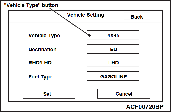
1. Select "Vehicle Type" button on "Vehicle Setting" screen.
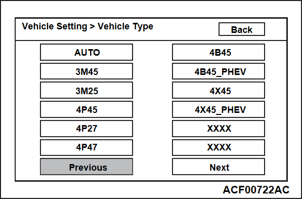
2. Select the vehicle type. Then, the screen will be switched back to "Vehicle Setting" screen automatically.
3. "Restart the program" will be displayed by selecting "Set" button on "Vehicle Setting" screen, and the setting will be configured.
Destination Setting
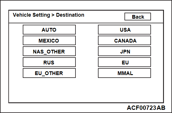
Sets the destination.
1. Select "Destination" button on "Vehicle Setting" screen.
2. Select destination. Then, the screen will be switched back to "Vehicle Setting" screen automatically.
3. "Restart the program" will be displayed by selecting "Set" button on "Vehicle Setting" screen, and the setting will be configured.
Handle Position Setting
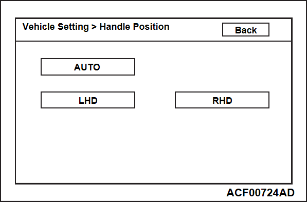
Sets the handle position.
1. Select "RHD/LHD" button on "Vehicle Setting" screen.
2. Select the handle position. Then, the screen will be switched back to "Vehicle Setting" screen automatically.
3. "Restart the program" will be displayed by selecting "Set" button on "Vehicle Setting" screen, and the setting will be configured.
Fuel Type Setting
Sets the fuel type.
1. Select "Fuel Type" button on "Vehicle Setting" screen.
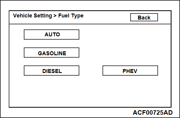
2. Select the fuel type. Then, the screen will be switched back to "Vehicle Setting" screen automatically.
3. "Restart the program" will be displayed by selecting "Set" button on "Vehicle Setting" screen, and the setting will be configured.
AUX Setting
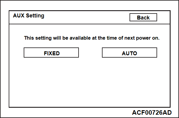
"AUX" button can be displayed on "Home" screen.
1. Select AUX Setting" button on "Service Menu" screen.
2. Select "FIXED" or "AUTO" button. Then, select "Back" button.
3. The next time the ignition switch is turned to "ACC" or "ON", the system setting will be active.
Touch Check
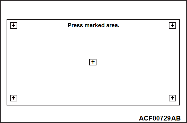
Check whether the touch panel is normal.
1. Select "Touch Check" button on "Service Menu" screen.
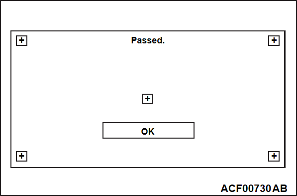
2. Change the button colors by touching each of the five buttons.
3. When all of the buttons are pressed, "OK button will appears together with a message. After the "OK" button is selected, it will be switched back to "Service Menu" screen.
Version Info
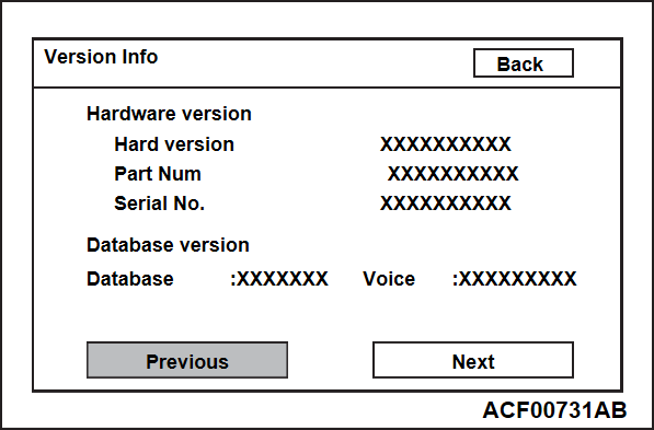
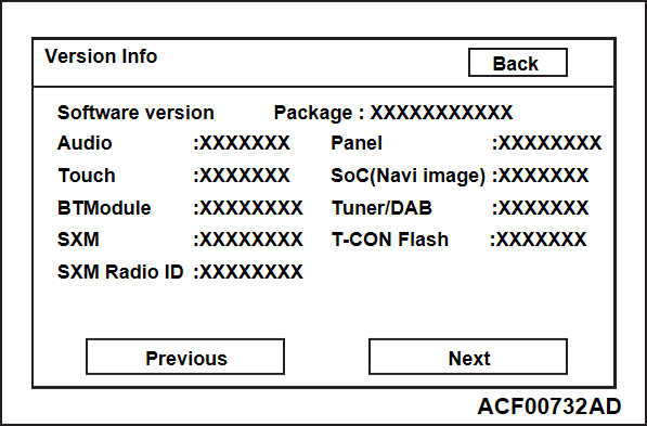
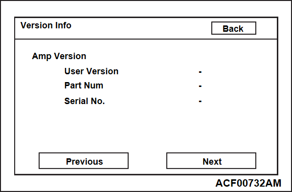
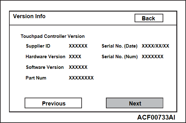
Displays the version information of the hardware, software, and database.
1. Select "Version Info" button on "Service Menu" screen.
2. A version information will be displayed. You should check the version information by pressing "Previous" and "Next" buttons.
Communication Check
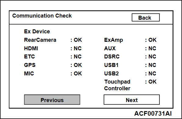
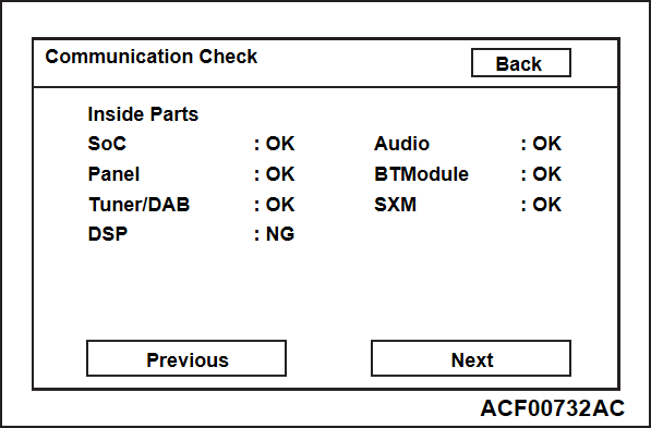
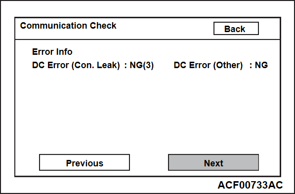
Check the connection status of each device.
1. Select "Communication Check" button on "Service Menu" screen.
2. "Now checking the external device connection." will appear, and then it will switch to "External Device Connection Result" screen.
- When an USB device is detected, it will be shown in USB1 and USB2 field in that order. The USB device won't disappear until its connector is disconnected. A device is shown as follows:
- CP: CarPlay connection (When a CarPlay-installed device is connected, the system recognizes it as "iPod" at first. Then it will be changed to "NC" and then "CP")
- AAP: AAP connection
- iPod: iPod connection
- USB: USB connection
- If the system detected no connection with equipment or is trying to detect it, "-" will be displayed.
- In case other than above, "NC" is displayed.
Vehicle Signal Info
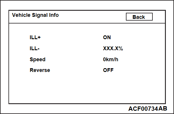
Displays statuses of illumination signal, vehicle speed signal and reverse signal.
1. Select "Vehicle Signal Info" button on "Service Menu" screen.
2. The current status of vehicle signal will be displayed.
- "ON" is displayed on "ILL+" item when the lighting switch is turned on (headlight or taillight illuminates). "OFF" is displayed when off. (If the system cannot receive any signal, "-" will be displayed.)
- "ILL-" displays an luminance of the illumination as percentage (0 to 100%). (If the system cannot receive any signal, "-" will be displayed.)
- "Speed" displays the vehicle speed.
- "Reverse": "ON" when the selector lever is at R position, and "OFF" when it is at the other position. (If the system cannot receive any signal, "-" will be displayed.)
Color Bar Check
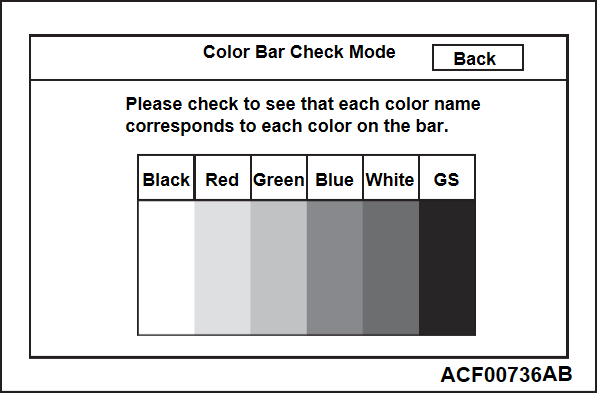
Checks the color display.
1. Select "Color Bar Check" button on "Service Menu" screen.
2. Six color bars are displayed.
3. When you touch one of the six color bars, the entire screen will displayed in the relevant color.
4. When you touch any spot on that screen, the monitor will return to the previous screen.
Speaker Check
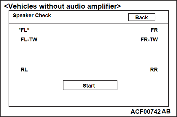
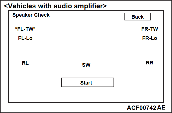
Checks the speakers.
1. Select "Speaker Check" button on "Service Menu" screen.
2. When you press "Start" button, each speaker will sound every one second according to the sequence listed in the table below. When the last speaker sounds, the test will terminate.
| note |
|
<Vehicle without audio amplifier>
|
<Vehicle without audio amplifier>
| Sequence | Tone | Speaker |
| 1 | Low | Front door speaker (LH), front tweeter (LH) |
| 2 | High | Front door speaker (LH), front tweeter (LH) |
| 3 | Low | Front door speaker (RH), front tweeter (RH) |
| 4 | High | Front door speaker (RH), front tweeter (RH) |
| 5 | Low | Rear door speaker (LH) |
| 6 | Low | Rear door speaker (RH) |
<Vehicle with audio amplifier>
|
<Vehicle with audio amplifier>
| Sequence | Tone | Speaker |
| 1 | High | Front tweeter (LH) |
| 2 | Low | Front door speaker (LH) |
| 3 | High | Front tweeter (RH) |
| 4 | Low | Front door speaker (RH) |
| 5 | Low | Rear door speaker (LH) |
| 6 | Low | Rear door speaker (RH) |
| 7 | Low | Subwoofer |
| note | The volume can be changed by operating the volume button. |
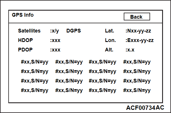
GPS Info
Displays the GPS-related information
1. Select "GPS Info" button on "Service Menu" screen.
2. The GPS-related information will be displayed.
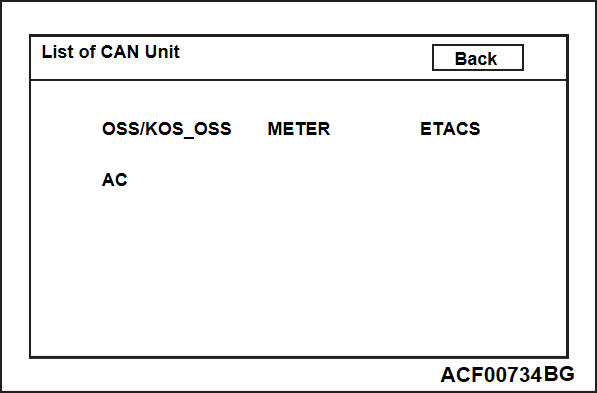
List of CAN Unit
Displays which CAN-compatible unit is connected with the multivision display.
1. Select "List of CAN Unit" button on "Service Menu" screen.
2. The system will determine which equipment is installed according to the connected equipment reference table.
|
| Screen indication | Equipment |
| OSS/KOS_OSS | KOS&OSS-ECU |
| METER | Combination meter |
| ETACS | ETACS-ECU |
| AC | A/C-ECU |
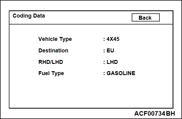
Coding Data
Displays the information you set on "Vehicle Setting" screen.
1. Select "Coding Data" button on "Service Menu" screen.
2. The information you set on "Vehicle Setting" screen will be displayed.
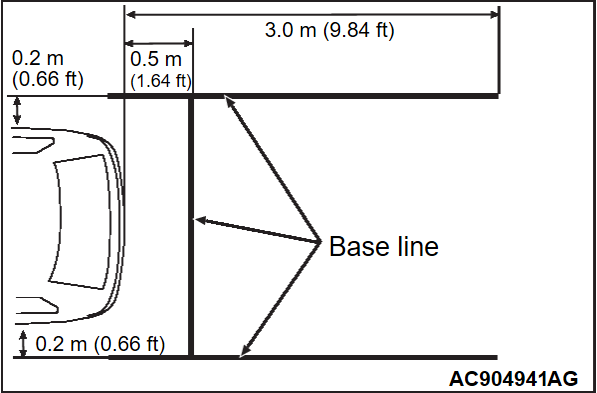
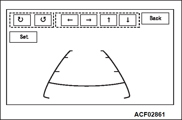
Camera Setting <Vehicles without multi around monitor>
Adjusts the guideline.
1. Select "Camera Setting" button on "Service Menu" screen.
2. Draw base lines 0.5 m (1.64 ft) behind the vehicle and width +0.4 m (1.31 ft) [+0.2 m (0.66 ft) each for right and left] and align the guide line over the base lines.
3. Adjust the guide line by operating "Rotate", "Left and right", "up and down" buttons.
4. When "Set" button is pressed, the setting will be saved and the screen will be switched back to "Service Menu" screen.
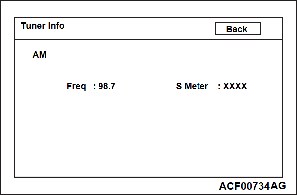
Radio Info
Displays the information on broadcasting method, reception frequency, and S meter.
1. Select "Radio Info" button on "Service Menu" screen.
2. "Tuner Info" screen will be displayed.
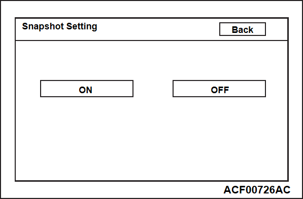
Snapshot Setting
Enables and disables the snapshot.
| note | When you press and hold "Home" button, the snapshot will allow you to save data into the first USB memory, which is connected with the multivision display. |
1. Select "Snapshot Setting" button on "Service Menu" screen.
2. Press "ON" button to enable the snapshot function.
3. When a "Back" button is pressed, the setting will be saved and the screen will be switched back to "Service Menu" screen.
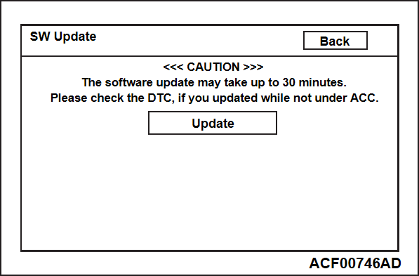
SW Update
Updates each software.
| note | Depending on a software capacity, it may take at most 30 minutes until the update completes. |
1. Select "SW Update" button on "Service Menu" screen.
2. Connect the USB memory.
3. Select "Update" button.
| note | This button will not be active when a new version update file for the multivision display is not stored in the USB memory. |
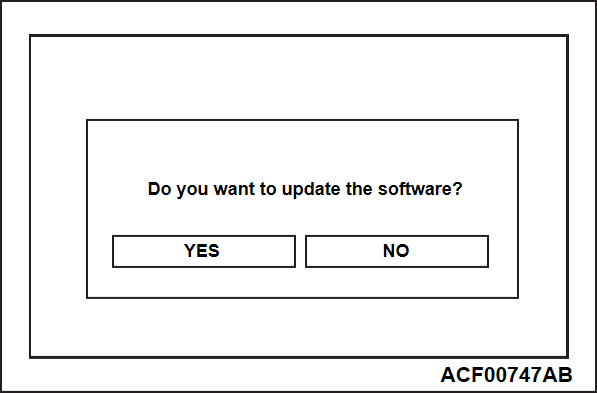
4. Select "Yes" button on the confirmation screen to start the update.
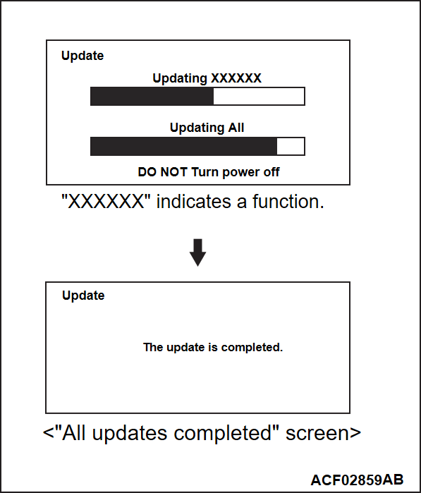
5. The program update process is as follows:
| note |
|
Export Log Data
Save an event log, which occurred in the multivision display, into the USB memory.
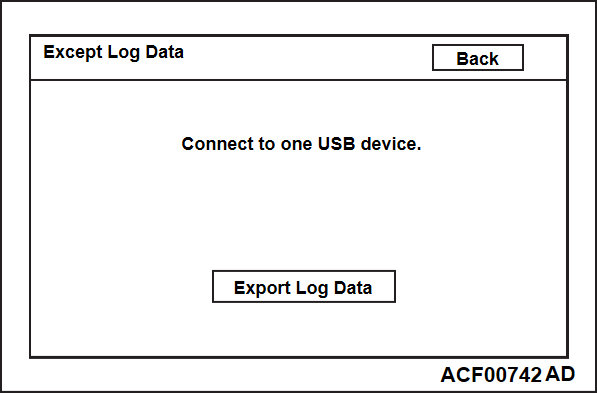
1. Select "Export Log Data" button on "Service Menu" screen.
2. Connect the USB memory.
3. Select "Export Log Data" button.
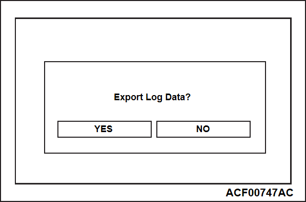
4. Select "Yes" button to start saving.
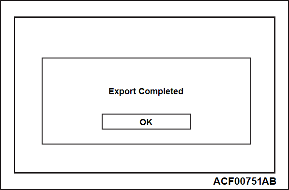
5. After the saving is complete, a message and "OK" button will be displayed. Select "OK" button.
Picture viewer
Displays the image data saved in the USB memory.
1. Select "Picture viewer" button on "Service Menu" screen.
- When you touch the left area on the screen, the previous screen will be displayed.
- When you touch the middle area on the screen, the screen will be switched back to "Service Menu" screen.
- When you touch the right area on the screen, the next screen will be displayed.
Mic Check
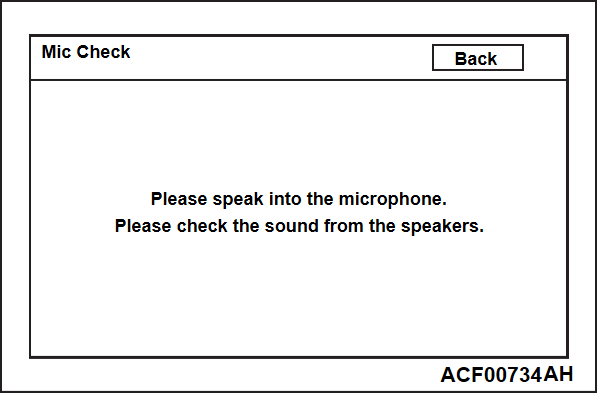
Responds to your voice through the microphone and generates the sound from a speaker.
1. Select "Mic Check" button on "Service Menu" screen.
2. When this message is shown, speak into the microphone and check the sound generated from the speaker.
HDMI Setting
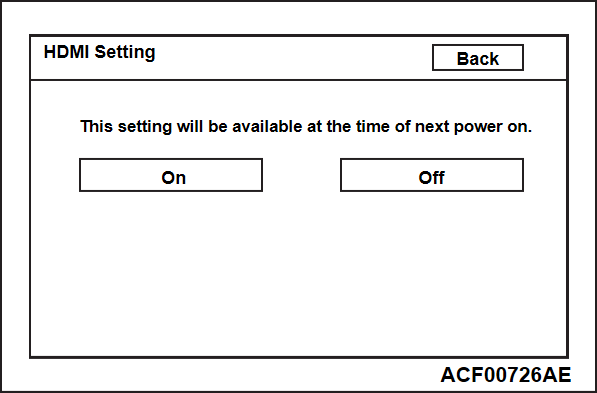
"HDMI" button can be displayed on "Home" screen.
1. Select "HDMI Setting" button on "Service Menu" screen.
2. Select "On" or "Off" button. Then, select "Back" button.
3. The next time the ignition switch is turned to "ACC" or "ON", the system setting will be active.
Error Log
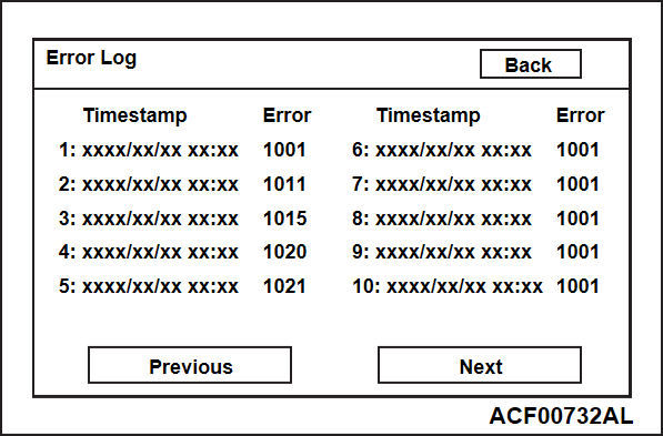
Shows the error log stored by the user operation.
1. Select "Error Log Data" button on "Service Menu" screen.
2. Displays the last 50 incidents by 10 incidents.
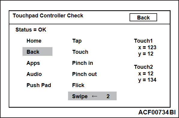
Touchpad Controller Check
Displays status of the touchpad controller.
1. Select "Touchpad Controller Check" button on "Service Menu" screen.
2. The following information is displayed.
Hardware switch operation
- Highlights the display of the pressed key.
Pad operation
- Highlights the display of the operation name according to the operation.
- The operation direction is also displayed with "Flick" and "Swipe".
- The number of touches is also displayed with "Touch" and "Swipe".
- Displays the coordinate information of the touched point, up to two points.
Touchpad controller status
- If the status of the Touchpad controller is normal, "Status" is displayed as "OK". If there is an abnormality, "NG" is displayed.
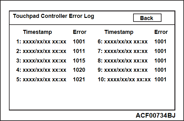
Touchpad Controller Log Data
Shows the error log stored by the touchpad controller.
1. Select "Touchpad Controller Error Log" button on "Service Menu" screen.
2. Displays the last 10 incidents.
![[Previous]](../../../buttons/fprev.png)
![[Next]](../../../buttons/fnext.png)
