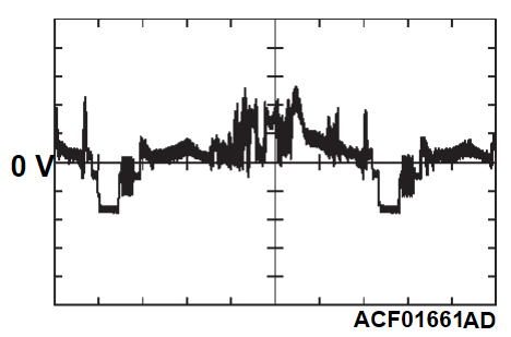
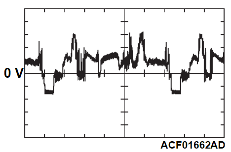
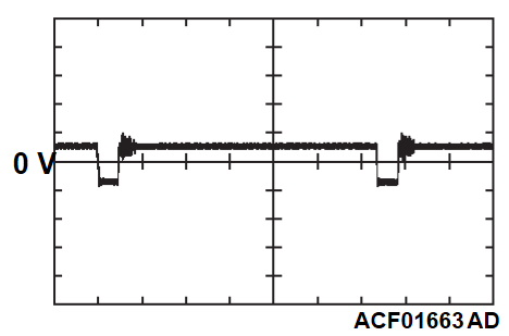
CHECK AT CAMERA-ECU TERMINAL
| Terminal No. | Terminal code | Check item | Check condition | Normal condition |
| 1 | CANH | CAN-C Hi | - | - |
| 2 - 4 | - | - | - | - |
| 5 | VSV | Side-view camera (LH) image input | Ignition switch: ON | Monitor a waveform with an oscilloscope. (DIV: 200 mV/10 ms) |
| 6 | S-EX | Ground for side-view camera (LH) image | Ignition switch: ON | 0.5 V or less |
| 7 | VRV | Rear-view camera image input | Ignition switch: ON | Monitor a waveform with an oscilloscope. (DIV: 200 mV/10 ms) |
| 8 | SVRV | Ground for rear-view camera image | Ignition switch: ON | 0.5 V or less |
| 9 | VNV | Front-view camera image input | Ignition switch: ON | Monitor a waveform with an oscilloscope. (DIV: 200 mV/10 ms) |
| 10 | Y-EX | Ground for side-view camera (RH) image | Ignition switch: ON | 0.5 V or less |
| 11 | VYV | Side-view camera (RH) image input | Ignition switch: ON | Monitor a waveform with an oscilloscope. (DIV: 200 mV/10 ms) |
| 12, 13 | - | - | - | - |
| 14 | VOUT | Camera image output | A camera image is displayed on the multivision display. | Monitor a waveform with an oscilloscope. (DIV: 200 mV/10 ms) |
| A camera image is NOT displayed on the multivision display. | Monitor a waveform with an oscilloscope. (DIV: 200 mV/10 ms) | |||
| 15 | ACCS | Power supply to side-view camera (LH) | Ignition switch: ON | 5.5 - 6.5 V |
| 16 | ACCR | Power supply to rear-view camera | Ignition switch: ON | 5.5 - 6.5 V |
| 17 | ACCN | Power supply to front-view camera | Ignition switch: ON | 5.5 - 6.5 V |
| 18 | ACCY | Power supply to side-view camera (RH) | Ignition switch: ON | 5.5 - 6.5 V |
| 19 | - | - | - | - |
| 20 | +B | Power supply to camera-ECU | Always | System voltage |
| 21 | CANL | CAN-C Lo | - | - |
| 22 - 28 | - | - | - | - |
| 29 | N-EX | Ground for front-view camera image | Ignition switch: ON | 0.5 V or less |
| 30 - 33 | - | - | - | - |
| 34 | SOUT | Ground for camera image output | Ignition switch: ON | 0.5 V or less |
| 35 | GNDS | Ground for side-view camera (LH) | Ignition switch: ON | 0.5 V or less |
| 36 | GNDR | Ground for rear-view camera | Ignition switch: ON | 0.5 V or less |
| 37 | GNDN | Ground for front-view camera | Ignition switch: ON | 0.5 V or less |
| 38 | GNDY | Ground for side-view camera (RH) | Ignition switch: ON | 0.5 V or less |
| 39 | - | - | - | - |
| 40 | GND | GND | Ignition switch: ON | 0.5 V or less |
![[Previous]](../../../buttons/fprev.png)
![[Next]](../../../buttons/fnext.png)


