DTC B1413: Passenger's (front) air bag module (1st squib) system (shorted to squib circuit power supply)
DTC B1493: Passenger's (front) air bag module (2nd squib) system (shorted to squib circuit power supply
DTC B1493: Passenger's (front) air bag module (2nd squib) system (shorted to squib circuit power supply
| caution |
|
CIRCUIT OPERATION
- The SRS-ECU judges how severe a collision is by detecting signals from the front impact sensors and the G-sensor in the SRS-ECU. If the impact is over a predetermined level, the SRS-ECU sends an ignition signal. At this time, the SRS air bag will inflate.
- The ignition signal is input to the air bag module to inflate the air bag.
DTC SET CONDITIONS
This DTC is set if there is abnormal resistance between the input terminals of the passenger's (front) air bag module (squib).
TROUBLESHOOTING HINTS
- Damaged harness wires and connectors
- Short to the power supply in the passenger's (front) air bag module (squib) harness
- Malfunction of the SRS-ECU
DIAGNOSIS
STEP 1. Using scan tool (M.U.T.-IIISE), diagnose the CAN bus line.
(1)
| caution | To prevent damage to scan tool (M.U.T.-IIISE), always turn the ignition switch to the "LOCK" (OFF) position before connecting or disconnecting scan tool (M.U.T.-IIISE). |
(2) Turn the ignition switch to the "ON" position.
(3) Diagnose the CAN bus line.
(4) Turn the ignition switch to the "LOCK" (OFF) position.
Is the CAN bus line found to be normal?
STEP 2. Recheck for diagnostic trouble code.
Check again if the DTC is set.
(1) Erase the DTC.
(2) Turn the ignition switch to the "ON" position.
(3) Check if the DTC is set.
(4) Turn the ignition switch to the "LOCK" (OFF) position.
Is the DTC set?
STEP 3. Diagnosis check by dummy resistor connection.
(1) Check that the negative battery terminal is disconnected. If the negative battery terminal is connected, disconnect it.
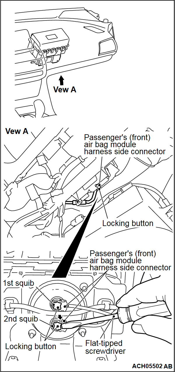
(2) Use the flat-tipped screwdriver to pull out the locking button of wiring harness side connector, and release the lock.
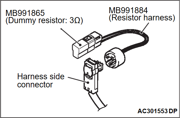
(3) Connect special tool dummy resistor (MB991865) to special tool resistor harness (MB991884).
(4)
| caution | Do not insert a probe directly into the terminal from the connector front side as the connector contact pressure may be weakened. |
Insert the resistor harness probe (special tool) from the back of harness side connector ASQ+, ASQ- line <B1413>.
Insert the resistor harness probe (special tool) from the back of harness side connector AQ2+, AQ2- line <B1493>.
(5)
| caution | Always DTC B1493 is set when checking DTC B1413. This is because the second side terminal is isolated when checking it. DTC B1493 is set but this is not a fault. In addition, always DTC B1413 is set when checking DTC B1493 because the first side terminal is isolated. |
Erase the DTC memory, and check the diagnostic trouble code.
(6) Disconnect the negative battery terminal.
Is the checked DTC set?
STEP 4. Voltage measurement at the SRS-ECU connector.
(1) Check that the negative battery terminal is disconnected. If the negative battery terminal is connected, disconnect it.
(2) Disconnect the SRS-ECU connector.
(3)
Use the flat-tipped screwdriver to pull out the locking button of wiring harness side connector, and release the lock.
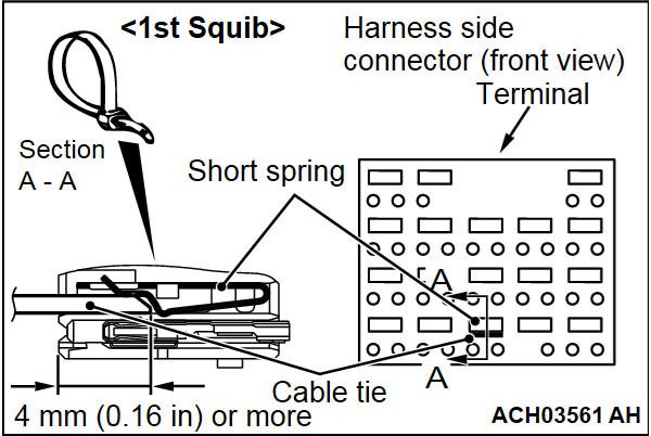
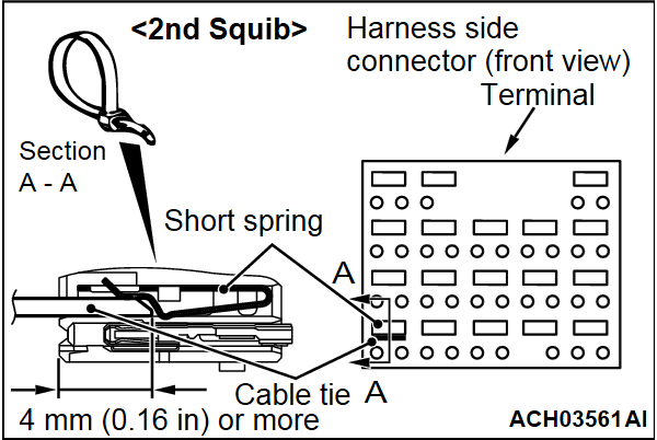
| danger | To release the connector short spring in the following operations, disconnect this harness side connector, and keep the squib circuit shorted. |
(4)
| caution | The short spring may not be released due to the insufficient insertion. Therefore, insert the insulator for 4 mm (0.16 inch) or more. |
Insert an insulator [3 mm (0.12 inch) wide, 0.5 mm (0.02 inch) thick] such as cable tie between the ASQ+, ASQ- line, and then release the short spring <B1413>.
Insert an insulator [3 mm (0.12 inch) wide, 0.5 mm (0.02 inch) thick] such as cable tie between the AQ2+, AQ2- line, and then release the short spring <B1493>.
(5) Connect the negative battery terminal.
(6) Ignition switch: ON
(7) Take the measurements below at the SRS-ECU harness side connector.
- Continuity between ASQ+, ASQ- line and body ground <B1413>
OK: 1 volt or less
- Continuity between AQ2+, AQ2- line and body ground <B1493>
OK: 1 volt or less
(8) Disconnect the negative battery terminal.
Is the check result normal?
 Repair the wiring harnesses ASQ+, ASQ- line <B1413> or AQ2+, AQ2- line <B1493> between the SRS-ECU connector and the passenger's (front) air bag module connector.
STEP 5. Using scan tool (M.U.T.-IIISE), check whether the DTC is set again.
Check again if the DTC is set.
(1) Erase the DTC.
(2) Turn the ignition switch to the "ON" position.
(3) Check if the DTC is set.
(4) Turn the ignition switch to the "LOCK" (OFF) position.
Is DTC B1413 (1st squib) or B1493 (2nd squib) set?
![[Previous]](../../../buttons/fprev.png)
![[Next]](../../../buttons/fnext.png)


