[Previous][Next]
DISASSEMBLY AND REASSEMBLY
 
 
caution
  • When the motor (integrated with EPS-ECU) is replaced, coding must be performed. When diagnostic trouble code No.U1195 "Coding not completed" is set in the motor (integrated with EPS-ECU), diagnose each diagnostic trouble code.
  • After the installation, perform a calibration for the EPS-ECU to learn the torque sensor neutral point (Refer to ).
  • Do not reuse the product that has been dropped because its internal components may be defective even if it has no apparent damage.
  • Always keep motor (EPS-ECU) away from the matter that generates magnetic force.
  • Handle carefully to prevent binding or damage of the wiring harness.
  • When replacing the EPS-ECU or electric steering lock, complete the chassis number registration (Refer to GROUP 00 - Precautions before Service - How to Perform Vin Writing ).
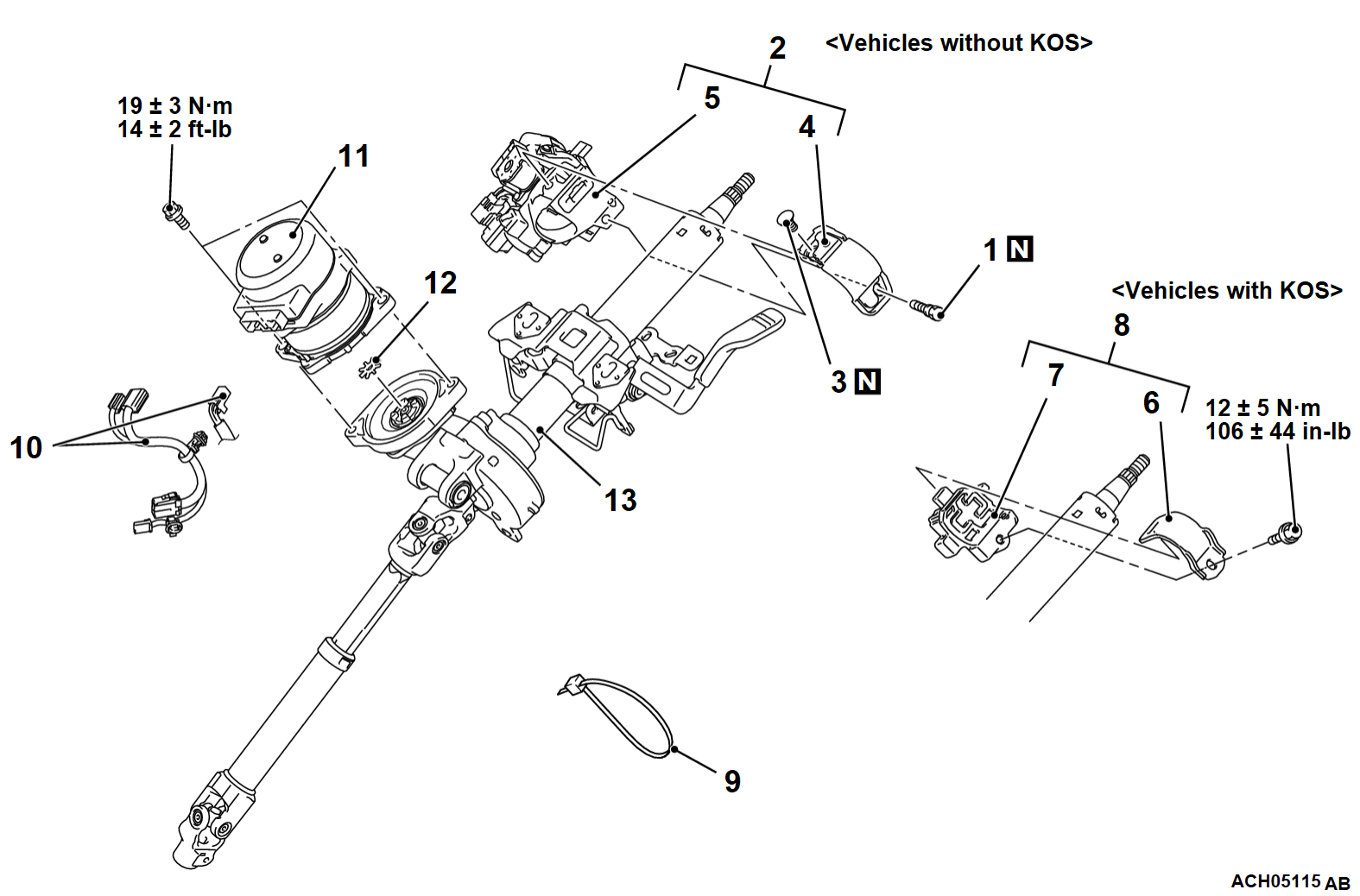
Disassembly steps
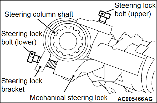
<<A>>>>D<<1.Steering lock bolt (lower)
2.Steering lock bracket and steering lock
<<A>>>>D<<3.Steering lock bolt (upper)
>>D<<4.Steering lock bracket
>>D<<5.Mechanical steering lock
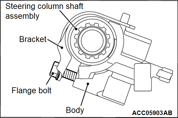
>>C<<6.Bracket
>>C<<7.Body
8.Steering lock dummy bracket assembly
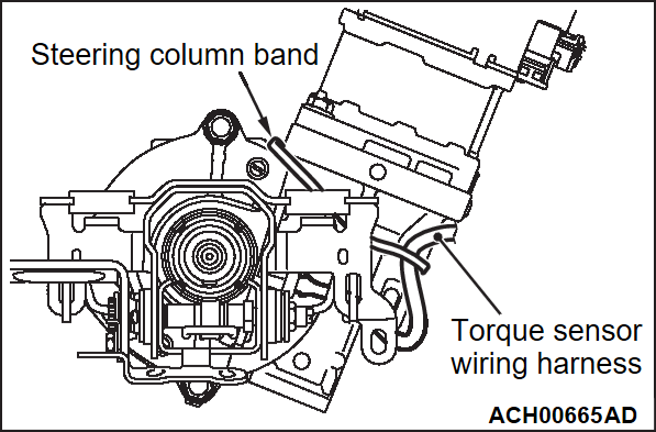
>>B<<9.Steering column band
<<B>>10.Motor (EPS-ECU) connector
>>A<<11.Motor (EPS-ECU)
<<B>>>>A<<12.Rubber spring*
13.Steering column shaft
note
  • A steering lock, a steering lock bracket and a steering lock bolt are supplied as a single unit. A mechanical steering lock assembly (a mechanical steering lock, a steering lock bracket, a steering lock bolt, a key reminder switch/key ring antenna assembly and an ignition switch are included.) is also supplied.<Vehicles without KOS>
  • When the steering lock assembly is supplied, the steering lock bracket is assembled to the steering lock and the steering lock bolt head (upper) is broken off.<Vehicles without KOS>
  • For removal and installation of key reminder switch/key ring antenna and ignition switch, Refer to GROUP 54A - Ignition Switch Removal and Installation .<Vehicles without KOS>
  • The steering lock dummy bracket assembly (including a bracket, a housing and a flange bolt) is installed to secure the paddle shift assembly.<Vehicles with KOS>
  • The steering lock dummy bracket is supplied not only as an assembly but also individually (the bracket, the housing and the flange bolt).<Vehicles with KOS>
  • When it is supplied as an assembly, the housing and the bracket have been assembled by the flange bolt.<Vehicles with KOS>
  • *: After removing the rubber spring, be careful not to lose them.
Required Special Tool:
  • MB990326: Preload socket
  • MB992678: Screw extractor
 
 
DISASSEMBLY SERVICE POINTS
 
 
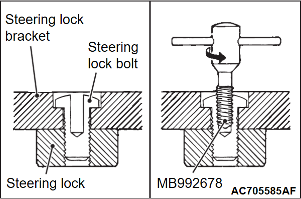
<<A>> STEERING LOCK BOLT REMOVAL
1. Use a drill to make a hole just deeply enough for the tap to stand on the steering lock bolt.
2. Remove the steering lock bolt using the screw extractor (Recommended tool: MB992684), or equivalent.


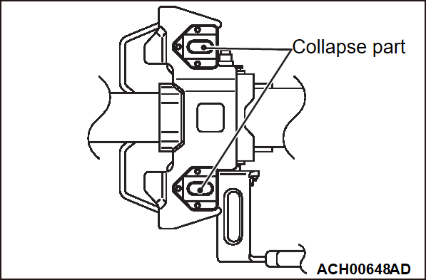
<<B>> MOTOR (EPS-ECU) REMOVAL
cautionDo not remove the collapse part (shown in the illustration).
1. Remove the wiring harness.
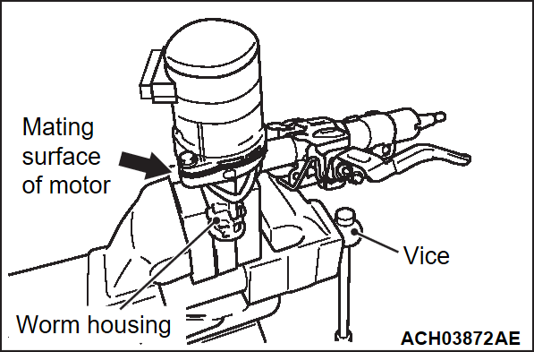
2. Adjust the electric motor so that its mating surface is horizontal, and then secure the worm gear housing on the steering column shaft with a vice.
caution
  • While clamping, be sure to keep the mating surface of the motor horizontal.
  • Clamp the worm housing in a vice via rag to prevent damage.
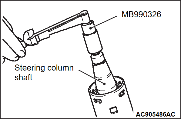
3. Install the nut to the end of the steering column shaft. Then use the preload socket (Special tool: MB990326) to rotate the shaft at a rate of one turn per 4 to 6 seconds, and then measure the total rotation torque.
note
  • Be sure to make a note of the measured value, as the value will be used when installing the motor.
  • Rotate by 180° in left and right directions from the neutral position, and measure the total rotation torque.
4. Remove the motor mounting bolts.


REASSEMBLY SERVICE POINT
 
 
>>A< RUBBER SPRING/MOTOR (EPS-ECU) INSTALLATION
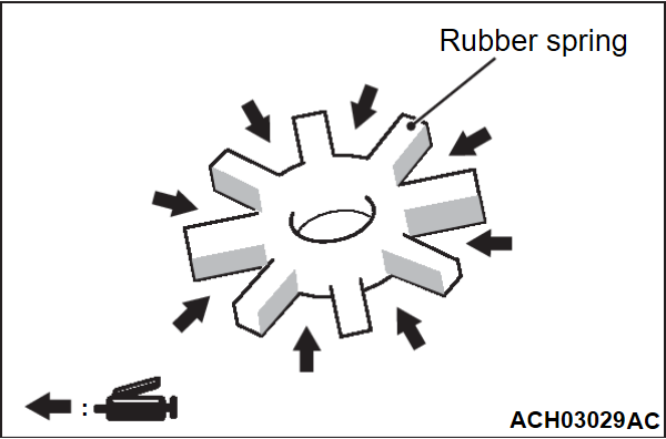
1. Apply grease to the rubber spring.
Specified grease: Rubber grease
Amount to use: 0.1 - 1.5 g (0.004 - 0.053 oz)
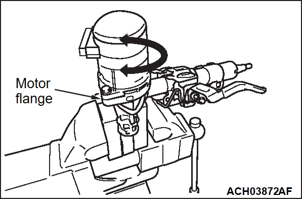
2. Insert the motor, and check that the motor flange moves with the bolts not tightened.
caution
  • Be careful to avoid scratches or intrusion of foreign materials on the mating surface of the motor and the worm housing.
  • Proceed carefully to ensure that the electric motor does not move, otherwise noise may be caused.
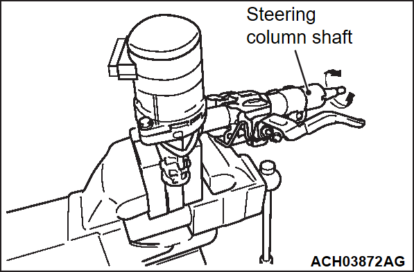
3. Rotate the steering column shaft at a speed of approximately one turn per second. While doing so, tighten the electric motor mounting bolts alternately by hand.
noteThe steering column shaft can be rotated in either direction (right and left).
4. Tighten the electric motor mounting bolts to the specified torque.
Tightening torque: 19 ± 3 N·m (14 ± 2 ft-lb)
5. Install the two nut to the end of the steering column shaft. Then use the preload socket (Special tool: MB990326) to rotate the shaft at a speed of one turn per 4 to 6 seconds, and then measure the total rotation torque.
note
  • Be sure to make a note of the measured value, as the value will be used when installing the motor.
  • Rotate by 180° in left and right directions from the neutral position, and measure the total rotation torque.
cautionIf the total rotation torque fluctuation compared with the value measured at removal is ±10% or more, remove the motor again and repeat installation steps 1, 2 and 3.
6. Connect the wiring harness.
7. Use a black felt pen to apply a mark near the label as shown as a visual indication that this work has been completed.


>>B<< STEERING COLUMN BAND INSTALLATION
caution
  • There must be no clearance between the torque sensor wiring harness and the housing.
  • On completion, check the followings.
    • The wiring harness must be free of twists, sharp bend.
    • The wiring harness must be secured without looseness.
Tie the wiring harness wires with the steering column band.


>>C<< BODY/BRACKET INSTALLATION <VEHICLES WITH KOS>
1. Insert the housing from the column shaft end, and then engage the protrusion on the housing with the recess on the steering column shaft assembly.
2. Tighten the flange bolt to the specified torque.
Tightening torque: 12 ± 5 N·m (106 ± 44 in-lb)


>>D<< MECHANICAL STEERING LOCK/STEERING LOCK BRACKET/STEERING LOCK BOLT INSTALLATION
1. Secure the steering lock bracket to the steering lock with steering lock bolt (Upper). Tighten the steering lock bolt until its head is broken off.
2. Insert the steering lock into the tip of the column shaft, fit the protrusion of the steering lock to the hole of the steering column shaft assembly, install the steering lock and tighten the steering lock bolt (lower) until its head is broken off.
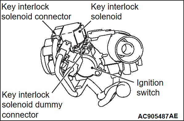
cautionAs for the mechanical steering lock connect the body side wiring harness connector to the key interlock solenoid connector. Do not connect the harness connector to the key interlock solenoid dummy connector.