DIAGNOSTIC FUNCTION
HOW TO CONNECT THE SCAN TOOL (M.U.T.-IIISE)
Required Special Tools:
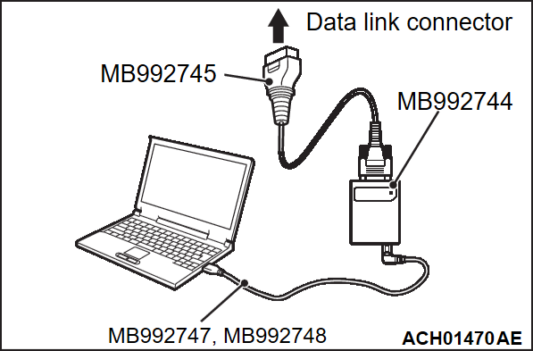
- MB992744: Vehicle communication interface-Lite (V.C.I.-Lite)
- MB992745: V.C.I.-Lite main harness A
- MB992747: V.C.I.-Lite USB cable short
- MB992748: V.C.I.-Lite USB cable long
| caution | To prevent damage to scan tool (M.U.T.-IIISE), always turn the ignition switch to the "LOCK" (OFF) position before connecting or disconnecting scan tool (M.U.T.-IIISE). |
1. Ensure that the ignition switch is at the "LOCK" (OFF) position.
2. Start up the personal computer.
3. Connect special tool MB992747/M992748 to special tool MB992744 and the personal computer.
4. Connect special tool MB992745 to special tool MB992744.
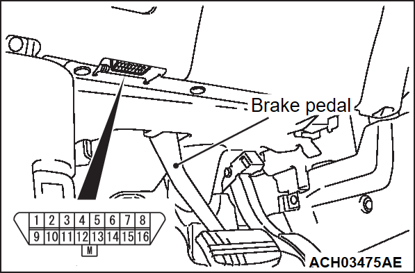
5. Connect special tool MB992745 to the data link connector.
| note | When the special tool MB992745 is connected to the data link connector, the special tool MB992744 indicator light will be illuminated in a green color. |
6. Start the M.U.T.-IIISE system on the personal computer.
| note | Disconnecting scan tool (M.U.T.-IIISE) is the reverse of the connecting sequence, first making sure that the ignition switch is at the "LOCK" (OFF) position. |
HOW TO READ AND ERASE DIAGNOSTIC TROUBLE CODES
Required Special Tools:
- MB992744: Vehicle communication interface-Lite (V.C.I.-Lite)
- MB992745: V.C.I.-Lite main harness A
- MB992747: V.C.I.-Lite USB cable short
- MB992748: V.C.I.-Lite USB cable long
| note | If the Battery voltage is low, diagnostic trouble codes will not be set. Check the battery if scan tool (M.U.T.-IIISE) does not display. |
1. Connect scan tool (M.U.T.-IIISE) to the data link connector.
2. Turn the ignition switch to the "ON" position.
3. Select "STV".
4. Select "ECPS/4WS".
5. Select "Diagnostic Trouble Code" to read the DTC.
6. If a DTC is set, it is shown.
7. Choose "Erase DTCs" to erase the DTC.
HOW TO READ DATA LIST
Required Special Tools:
- MB992744: Vehicle communication interface-Line (V.C.I.-Line)
- MB992745: V.C.I.-Line main harness A (for vehicle with CAN communication)
- MB992747: V.C.I.-Line USB cable short
- MB992748: V.C.I.-Line USB cable long
1. Connect scan tool (M.U.T.-IIISE) to the data link connector.
2. Turn the ignition switch to the "ON" position.
3. Select "STV".
4. Select "ECPS/4WS".
5. Select "Data List."
6. Choose an appropriate item and select the "OK" button.
HOW TO PERFORM ACTUATOR TEST
Required Special Tools:
- MB992744: Vehicle communication interface-Line (V.C.I.-Line)
- MB992745: V.C.I.-Line main harness A (for vehicle with CAN communication)
- MB992747: V.C.I.-Line USB cable short
- MB992748: V.C.I.-Line USB cable long
1. Connect scan tool (M.U.T.-IIISE) to the data link connector.
2. Turn the ignition switch to the "ON" position.
3. Select "STV".
4. Select "ECPS/4WS".
5. Select "Actuator Test".
6. Choose an appropriate item and select the "OK" button.
HOW TO DIAGNOSE THE CAN BUS LINES
Required Special Tools:
- MB992744: Vehicle communication interface-Lite (V.C.I.-Lite)
- MB992745: V.C.I.-Lite main harness A
- MB992747: V.C.I.-Lite USB cable short
- MB992748: V.C.I.-Lite USB cable long
1. Connect scan tool (M.U.T.-IIISE) to the data link connector.
2. Turn the ignition switch to the "ON" position.
3. Select "CAN bus diagnosis" from the system select screen.
4. When the optional equipment screen is displayed, choose the one which the vehicle is fitted with, and then select the "OK" button.
CHECK OF FREEZE FRAME DATA
The freeze frame data can be checked by using scan tool (M.U.T.-IIISE).
When detecting the trouble and storing the DTC, the ECU connected to CAN bus line obtains the data when the DTC is confirmed, and then stores the ECU status of that time. By analyzing each data from scan tool (M.U.T.-IIISE), the troubleshooting can be performed more efficiently. The displayed items are as the table below.
Display item list
| Item No. | Item name | Data item | Unit |
| 01 | Odometer | Total driving distance when the DTC is generated | km/mile |
| 02 | Ignition cycle | Number of times the ignition switch is turned "ON" or "LOCK (OFF)" after the past failure transition | Number of counts is display |
| 04 | Accumulated minute | Cumulative time for current malfunction of DTC | min |
| 05 | Torque sensor voltage1 | Voltage of the torque sensor 1 when the DTC is generated | V |
| 06 | Torque sensor voltage2 | Voltage of the torque sensor 2 when the DTC is generated | V |
| 07 | Torque sensor power supply voltage1 | Voltage of torque sensor 1 power supply when the DTC is generated | V |
| 08 | Torque sensor power supply voltage2 | Voltage of torque sensor 2 power supply when the DTC is generated | V |
| 09 | Rotation angle sensor Vx1 | Voltage of the motor angle sensor Vx1 signal when the DTC is generated | V |
| 10 | Rotation angle sensor Vx2 | Voltage of the motor angle sensor Vx2 signal when the DTC is generated | V |
| 11 | Rotation angle sensor Vy1 | Voltage of the motor angle sensor Vy1 signal when the DTC is generated | V |
| 12 | Rotation angle sensor Vy2 | Voltage of the motor angle sensor Vy2 signal when the DTC is generated | V |
| 13 | System1 U phase current | Current 1 U phase current when the DTC is generated | A |
| 14 | System1 V phase current | Current 1 V phase current when the DTC is generated | A |
| 15 | System1 W phase current | Current 1 W phase current when the DTC is generated | A |
| 16 | System2 U phase current | Current 2 U phase current when the DTC is generated | A |
| 17 | System2 V phase current | Current 2 V phase current when the DTC is generated | A |
| 18 | System2 W phase current | Current 2 W phase current when the DTC is generated | A |
| 19 | System1 U terminal voltage | Voltage 1 U phase voltage when the DTC is generated | V |
| 20 | System1 V terminal voltage | Voltage 1 V phase voltage when the DTC is generated | V |
| 21 | System1 W terminal voltage | Voltage 1 W phase voltage when the DTC is generated | V |
| 22 | System2 U terminal voltage | Voltage 2 U phase voltage when the DTC is generated | V |
| 23 | System2 V terminal voltage | Voltage 2 V phase voltage when the DTC is generated | V |
| 24 | System2 W terminal voltage | Voltage 2 W phase voltage when the DTC is generated | V |
| 25 | System1 PIG voltage | Voltage of the motor (line 1) when the DTC is generated | V |
| 26 | System2 PIG voltage | Voltage of the motor (line 2) when the DTC is generated | V |
| 27 | IG voltage | Voltage of the EPS-ECU when the DTC is generated | V |
| 28 | Vehicle speed | Vehicles speed when the DTC is generated | km/h/mph |
| 29 | Steering wheel angle | Steering angle when the DTC is generated | deg |
| 30 | Engine speed | Engine speed when the DTC is generated | rpm |
| 31 | Ready condition | - | - |
| 32 | Steering torque | Steering assist torque when the DTC is generated | - |
| 33 | Motor q-axis detection current | Current of motor when the DTC is generated | A |
| 34 | Motor q-axis request current | Indication current to motor when the DTC is generated | A |
| 35 | Steering wheel angular velocity | Steering angular velocity when the DTC is generated | deg/s |
| 36 | Thermistor temperature | Thermistor temperature when the DTC is generated | °C/°F |
| 37 | Software operating state | - | - |
| 38 | Control mode | - | - |
| 39 | Detail diagnostic code | - | - |
![[Previous]](../../../buttons/fprev.png)
![[Next]](../../../buttons/fnext.png)

