DTC C1041 FL Wheel Speed Tone Performance
DTC C1042 FR Wheel Speed Tone Performance
DTC C1043 RL Wheel Speed Tone Performance
DTC C1044 RR Wheel Speed Tone Performance
DTC C1042 FR Wheel Speed Tone Performance
DTC C1043 RL Wheel Speed Tone Performance
DTC C1044 RR Wheel Speed Tone Performance
| caution |
OPERATION
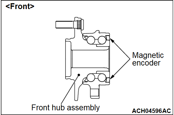
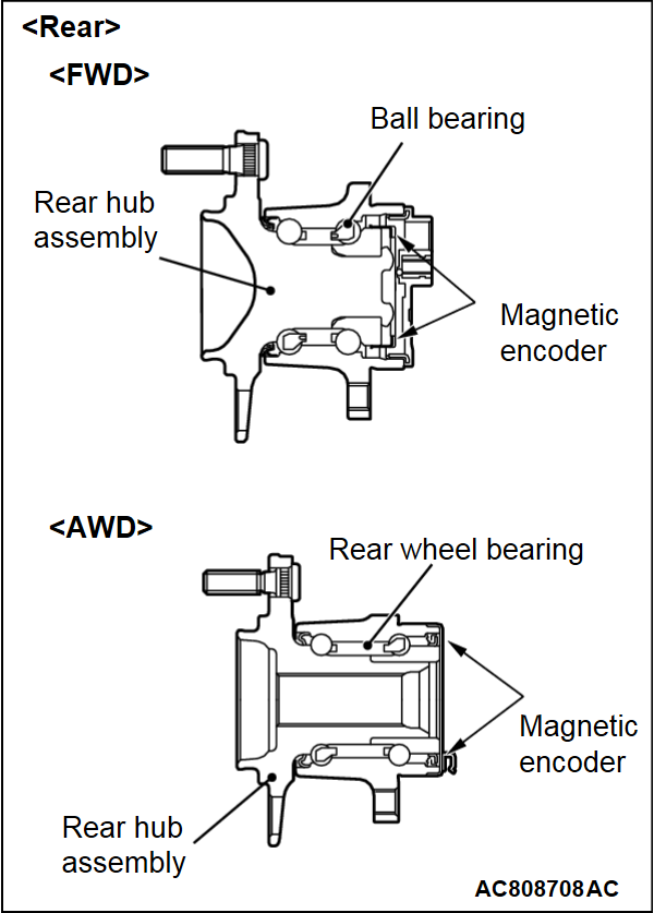
- The wheel speed sensor is a kind of a pulse generator. It consists of encoders (a plate on which north and south pole sides of the magnets are arranged alternately) for detecting the wheel speed which rotates at the same speed of the wheels and wheel speed sensors. This sensor outputs frequency pulse signals in proportion to the wheel speed.
- The pulse signals, which the wheel speed sensor creates, are sent to ASC-ECU. ASC-ECU uses the frequency of the pulse signals to determine the wheel speed.
DTC SET CONDITIONS
ASC-ECU monitors the signals from each wheel speed sensor while the vehicle is being driven. If any periodical drop is found in these sensor signals, ASC-ECU will set the relevant DTC.
PROBABLE CAUSES
- Wheel bearing malfunction
- Deformation of the wheel speed detection encoder
- Adhesion of foreign materials on the wheel speed detection encoder
- ASC-ECU malfunction
- The number of poles on the Magnetic encoder for wheel speed detection (N-pole and S-pole) is changed
DIAGNOSIS
STEP 1. Using scan tool (M.U.T.-IIISE), diagnose the CAN bus line.
(1)
| caution | To prevent damage to scan tool (M.U.T.-IIISE), always turn the ignition switch to the "LOCK" (OFF) position before connecting or disconnecting scan tool (M.U.T.-IIISE). |
(2) Turn the ignition switch to the "ON" position.
(3) Diagnose the CAN bus line.
(4) Turn the ignition switch to the "LOCK" (OFF) position.
Is the check result normal?
STEP 2. DTC recheck after resetting CAN bus lines.
STEP 3. Check for wheel bearing looseness.
Is the check result normal?
STEP 4. Check of wheel speed detection encoder.
Check the encoder for adhesion of foreign materials or deformation.
Is the check result normal?
: Remove the foreign materials and clean the encoder so as not to disturb the magnetization pattern on it while taking care of the magnet, magnetic substance, and magnetic attraction.
STEP 5. Check whether the DTC is set again.
(1) Erase the DTC.
(2) Drive the vehicle at 20 km/h (12 mph) or higher.
| note | The ABS warning light does not turn OFF in some cases unless the vehicle runs at 20 km/h (12 mph) or higher. |
Is DTC C1041, C1042, C1043 or C1044 set?
 This diagnosis is complete.
![[Previous]](../../../buttons/fprev.png)
![[Next]](../../../buttons/fnext.png)


