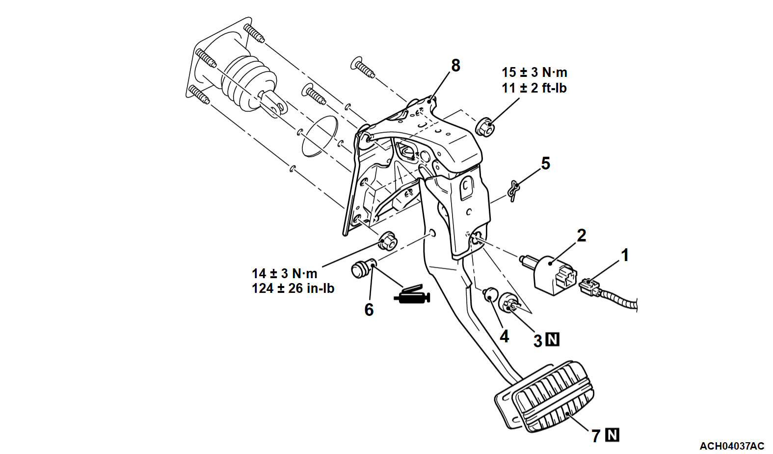
REMOVAL AND INSTALLATION
| caution | Do not apply lubricant (grease or silicon system sprayer etc.) to the switch and the switch installation section to avoid malfunction of the switch. In addition, do not use gloves which have lubricant (grease or silicon system sprayer etc.) on them. |
Pre-removal Operation | Post-installation Operation |
REMOVAL SERVICE POINT
<<A>> BRAKE PEDAL ASSEMBLY REMOVAL
From the engine compartment side, remove the brake pedal assembly while pulling the brake booster.
INSTALLATION SERVICE POINT
>>A<< STOPLIGHT SWITCH / STOPLIGHT SWITCH CONNECTOR INSTALLATION
Install the stoplight switch in the following procedure:
1. Insert the stoplight switch into the key hole on the plate.
2. While holding the brake pedal upwards, push in the stoplight switch to the stop position.
3. Lock the stoplight switch body by twisting it clockwise.
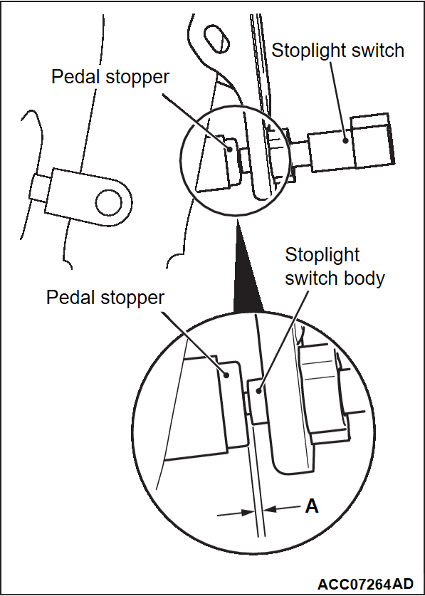
4. Check that the clearance between the stoplight switch and the pedal stopper is within the standard value.
Standard value (A): 0.5 - 1.5 mm (0.02 - 0.06 inch)
5.
| caution | Make sure that the stoplight is not illuminated when the brake pedal is not depressed. |
Connect the stoplight switch connector.
![[Previous]](../../../buttons/fprev.png)
![[Next]](../../../buttons/fnext.png)


