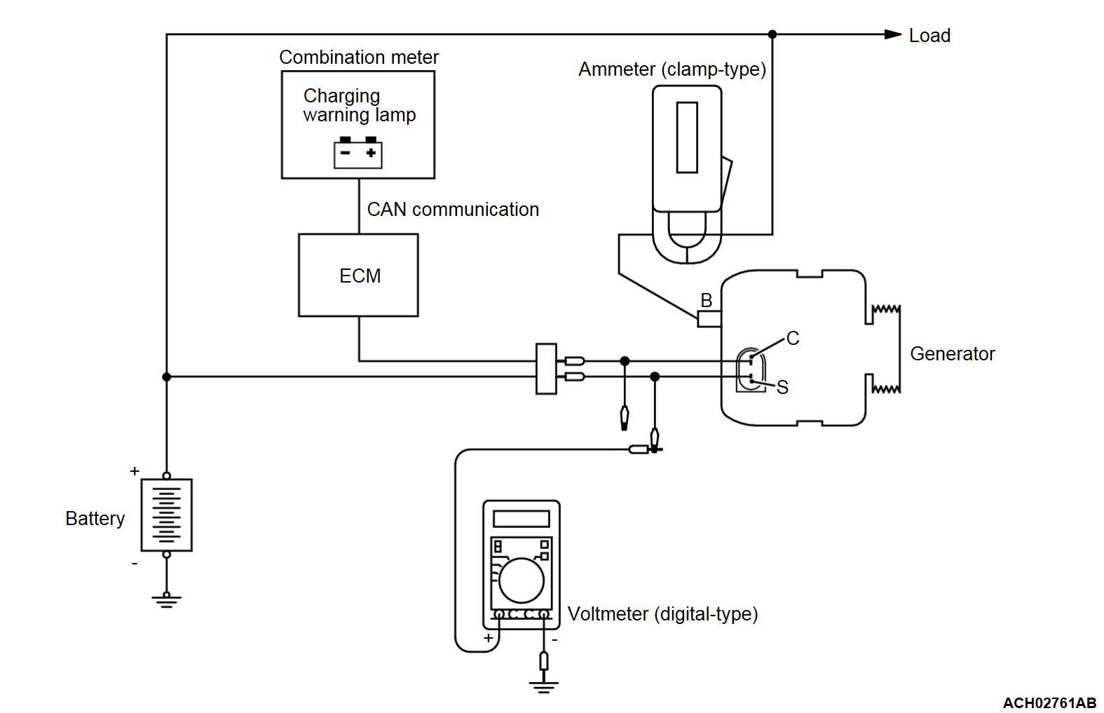
REGULATED VOLTAGE TEST
Required Special Tools:
- MB992744: Vehicle communication interface-Lite (V.C.I.-Lite)
- MB992745: V.C.I.-Lite main harness A
- MB992747: V.C.I.-Lite USB cable short
- MB992748: V.C.I.-Lite USB cable long
This test determines whether the voltage regulator correctly controlling the generator output voltage.
1. Always be sure to check the following before the test.
2. Turn the ignition switch to the "LOCK" (OFF) position.
3. Disconnect the negative battery cable.
4. Use the special tool Generator test harness to connect a digital voltmeter between the generator "S" terminal and ground [Connect the (+) lead of the voltmeter to the "S" terminal, and then connect the (-) lead of the voltmeter to a secure ground or to the battery (-) terminal].
5. Set a clamp-type DC test ammeter to the generator "B" terminal output wire.
6. Reconnect the negative battery cable.
7. Connect the scan tool (M.U.T.-IIISE).
8. Turn the ignition switch to the "ON" position and check that the reading on the voltmeter is equal to the battery voltage.
| note | If the voltage is 0 V, the cause is probably an open circuit in the wire or fusible link between the generator "S" terminal and the battery (+) terminal. |
9. Turn all lights and accessories off.
10. Start the engine.
| note | Do not drive the vehicle after the engine starts. |
11. Increase the engine speed to 2,500 r/min.
12. Read the value displayed on the voltmeter when the generator output current generator becomes 15 A or less.
13. If the voltage reading conforms to the value in the voltage regulation table, then the voltage regulator is operating normally.
If the voltage is not within the standard value, there is a malfunction of the voltage regulator or of the generator.
14. After the test, lower the engine speed to the idle speed.
15. Turn the ignition switch to the "LOCK" (OFF) position.
16. Disconnect the scan tool (M.U.T.-IIISE).
17. Disconnect the negative battery cable.
18. Disconnect the ammeter and voltmeter.
19. Remove the special tool, and return the connector to the original condition.
20. Connect the negative battery cable.
Voltage Regulation Table
STANDARD VALUE:
| Inspection terminal | Voltage regulator ambient temperature °C (°F) | Voltage V |
| Terminal "S" | -20 (-4) | 14.3 - 15.3 |
| 20 (68) | 13.9 - 14.9 | |
| 60 (140) | 13.5 - 14.5 | |
| 80 (176) | 13.3 - 14.3 |
![[Previous]](../../../buttons/fprev.png)
![[Next]](../../../buttons/fnext.png)

