INSPECTION PROCEDURE USING AN OSCILLOSCOPE
INTAKE CAMSHAFT POSITION SENSOR AND CRANKSHAFT POSITION SENSOR
Required Special Tool:
- MB991709: Test Harness
Measurement Method
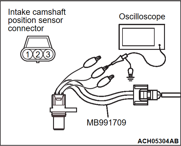
1. Disconnect the intake camshaft position sensor connector, and connect the test harness special tool (MB991709) between the separated connector (All terminals should be connected).
2. Connect the oscilloscope probe to intake camshaft position sensor connector terminal No. 2.
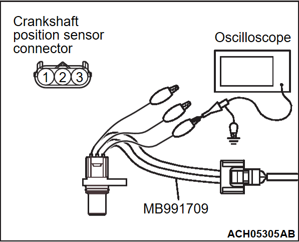
3. Disconnect the crankshaft position sensor connector, and connect the test harness special tool (MB991709) between the separated connector (All terminals should be connected).
4. Connect the oscilloscope probe to crankshaft position sensor connector terminal No. 1.
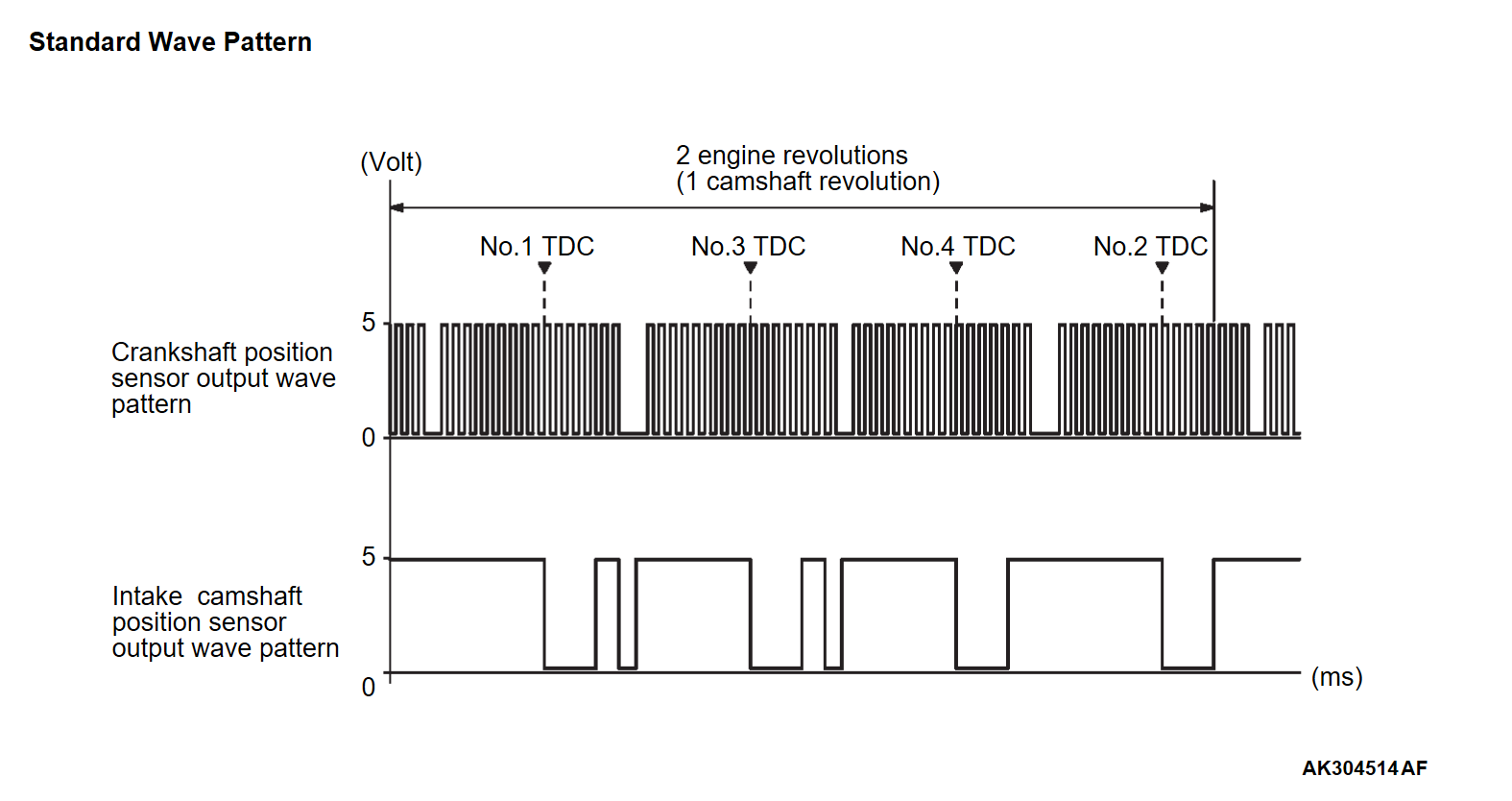
Standard Wave Pattern
| Observation condition | |
| Function | Special pattern |
| Selector switch of oscilloscope probe | × 1 |
| AC-GND-DC | DC |
| TIME/DIV. | 50 ms |
| VOLTS/DIV. | 5 volts |
| Engine condition | Idle |
Wave Pattern Observation Points
- Verify that the sensor signal frequency increase as the engine speed rises.
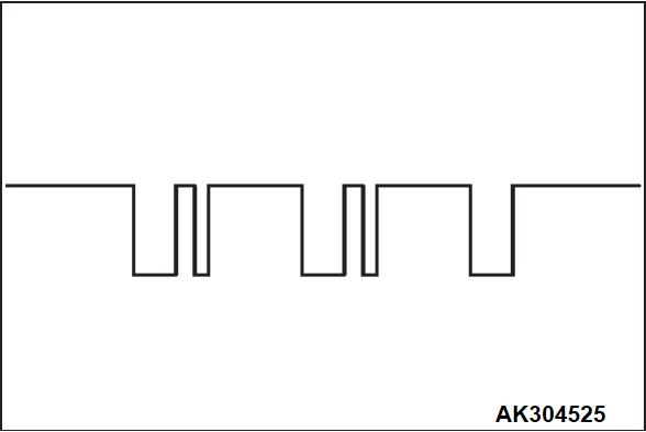
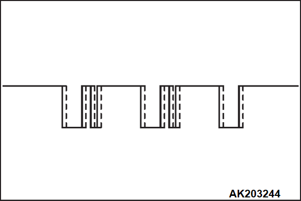
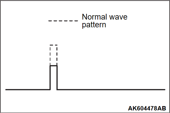
Examples of Abnormal Wave Patterns
Example 1
- Cause of problem
- Sensor interface malfunction.
- Wave pattern characteristics
- Rectangular wave pattern is output even when the engine is not started.
Example 2
- Cause of problem
- Loose timing chain.
- Abnormality in sensor disc.
- Wave pattern characteristics
- Wave pattern is displaced to the left or right.
EXHAUST CAMSHAFT POSITION SENSOR AND CRANKSHAFT POSITION SENSOR
Required Special Tool:
- MB991709: Test Harness
Measurement Method
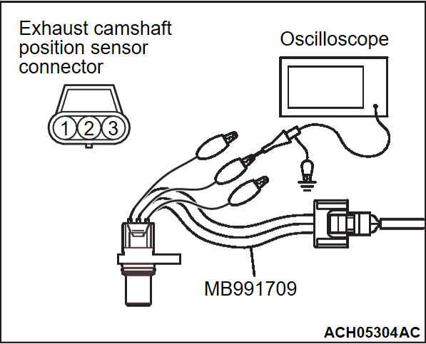
1. Disconnect the exhaust camshaft position sensor connector, and connect the test harness special tool (MB991709) between the separated connector (All terminals should be connected).
2. Connect the oscilloscope probe to exhaust camshaft position sensor connector terminal No. 2.
3. Disconnect the crankshaft position sensor connector, and connect the test harness special tool (MB991709) between the separated connector (All terminals should be connected).
4. Connect the oscilloscope probe to crankshaft position sensor connector terminal No. 1.
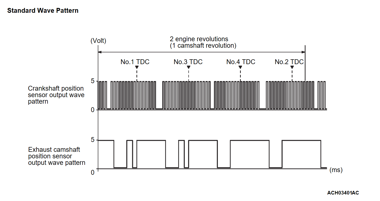
Standard Wave Pattern
| Observation condition | |
| Function | Special pattern |
| Selector switch of oscilloscope probe | × 1 |
| AC-GND-DC | DC |
| TIME/DIV. | 50 ms |
| VOLTS/DIV. | 5 V |
| Engine condition | Idle |
Wave Pattern Observation Points
- Verify that the relative position of the exhaust camshaft position sensor's output wave changes when the low load operation changes to the high load operation.
Examples of Abnormal Wave Patterns
Example 1
- Cause of problem
- Sensor interface malfunction.
- Wave pattern characteristics
- Rectangular wave pattern is output even when the engine is not started.
Example 2
- Cause of problem
- Loose timing chain.
- Abnormality in sensor disc.
- Wave pattern characteristics
- Wave pattern is displaced to the left or right.
INJECTOR
Required Special Tool:
- MB991658: Test Harness
Measurement Method
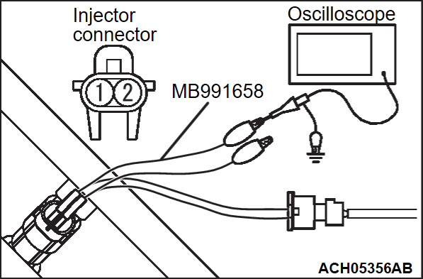
- Disconnect the injector connector, and connect the test harness special tool (MB991658) between the separated connector. (All terminals should be connected.)
- Connect the oscilloscope probe to injector connector terminal No. 2.
Standard Wave Pattern
| Observation conditions | |
| Function | Special pattern |
| Selector switch of oscilloscope probe | × 10 |
| AC-GND-DC | DC |
| TIME/DIV. | 0.5 ms |
| VOLTS/DIV. | 1 V |
| Engine condition | Idle |
Wave Pattern Observation Points
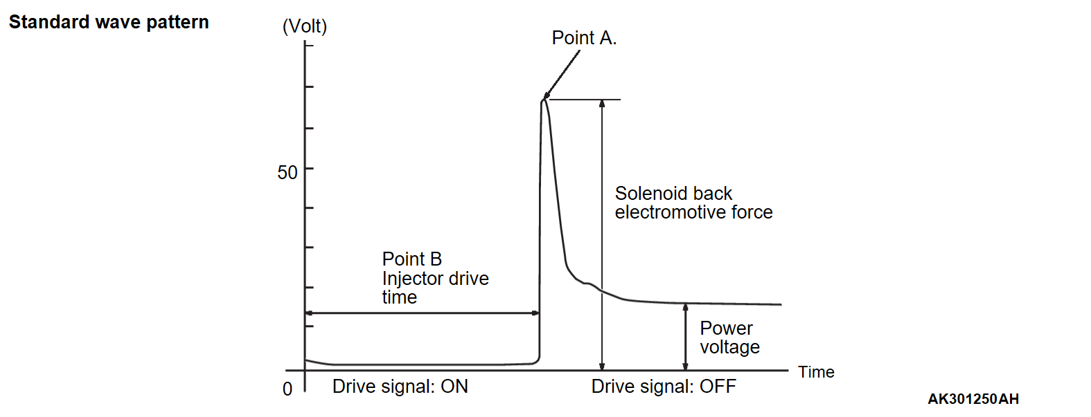
- Point A: Height of injector coil induced voltage.
| CONTRAST WITH STANDARD WAVE PATTERN | PROBABLE CAUSE |
| Injector coil induced voltage is low or doesn't appear at all | Short in the injector solenoid |
Point B: Injector drive time
- The injector drive time should be synchronized with the scan tool tester display.
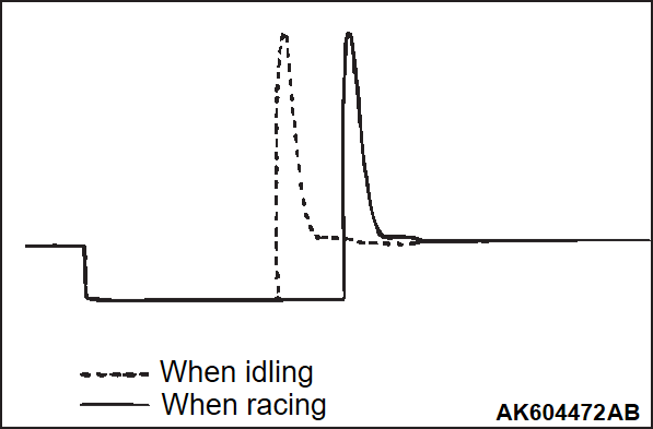
- When the engine is suddenly revved, the drive time will be greatly extended at first, but the drive time will soon return to original length.
IGNITION COIL AND IGNITION POWER TRANSISTOR
Required Special Tool:
- MB991658: Test Harness
Measurement Method
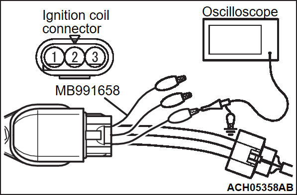
- Disconnect the ignition coil connector, and connect test harness special tool (MB991658) between the separated connector. (All terminals should be connected.)
- Connect the oscilloscope probe to ignition coil connector terminal No. 1.
Standard Wave Pattern
| Observation condition | |
| Function | Special pattern |
| Selector switch of oscilloscope probe | × 1 |
| AC-GND-DC | DC |
| TIME/DIV. | 50 ms |
| VOLTS/DIV. | 5 V |
| Engine condition | Idle |
Wave Pattern Observation Points
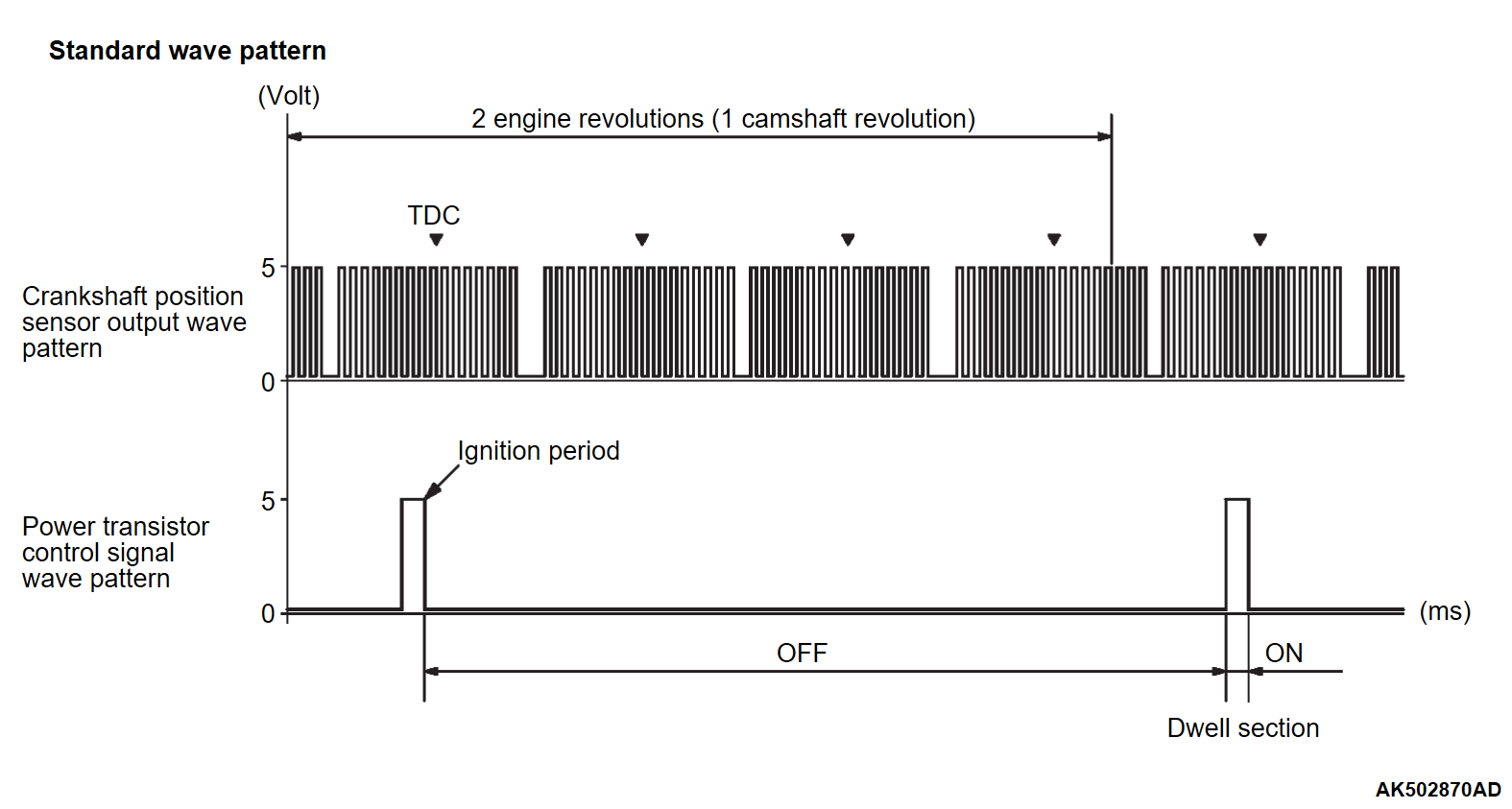
- Point: The power transistor control signal (ignition timing) is advanced when the engine speed is increased.
| CONDITION OF WAVE PATTERN BUILD-UP SECTION AND MAXIMUM VOLTAGE | PROBABLE CAUSE |
| Voltage value is too low | Open-circuit in ignition primary circuit |
![[Previous]](../../../buttons/fprev.png)
![[Next]](../../../buttons/fnext.png)
