![[Previous]](../../../buttons/fprev.png)
![[Next]](../../../buttons/fnext.png)
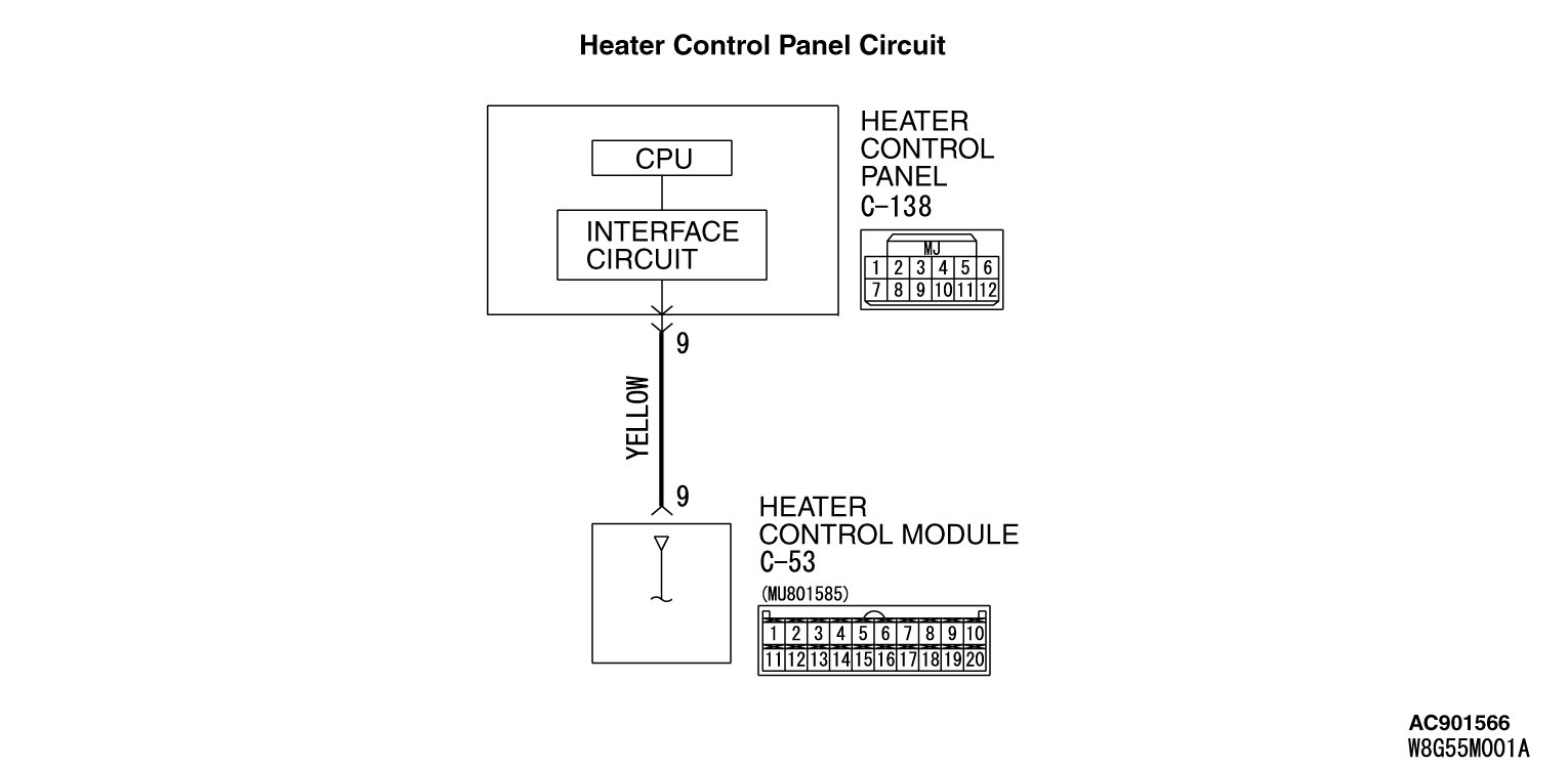
DTC B1003: Mode
Dial SW Error <Vehicles without A/C>
|
|
DTC B1003 will be set when the heater control module cannot receive the signal of mode
selection knob.
|
|
|
TECHNICAL DESCRIPTION (COMMENT)
|
|
|
Current trouble
- The heater control module, the heater control panel, or connector(s) or wiring between
the two may be defective.
|
|
|
Past trouble
- If DTC B1003 is stored as a past trouble, carry out diagnosis with particular emphasis
on wiring and connector(s) between the heater control module and the heater control panel. If
the connectors and wiring are normal, and obviously the ECU is the cause of the trouble, replace
the ECU. If in doubt, do not replace the ECU.
|
|
|
- Malfunction of connector.
- Malfunction of the harness.
- Malfunction of the heater control panel.
- Malfunction of the heater control module.
|
|
|
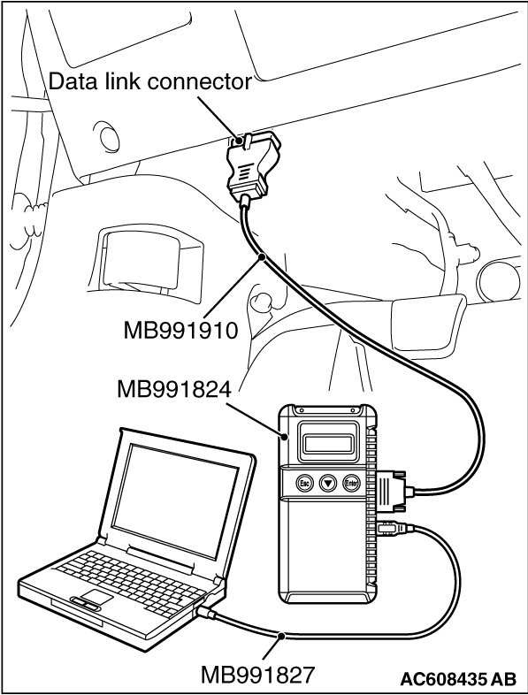
Required Special Tool:
- MB991958: Scan Tool (M.U.T.-III Sub Assembly)
- MB991824: Vehicle Communication Interface (V.C.I.)
- MB991827: M.U.T.-III USB Cable
- MB991910: M.U.T.-III Main Harness A
|
|
|
STEP 1. Using scan tool MB991958, diagnose the CAN bus line
|
|
(1)
| caution |
To prevent damage to scan tool MB991958, always turn the ignition switch
to the "LOCK" (OFF) position before connecting or disconnecting scan tool MB991958.
|
Connect scan tool MB991958. Refer to "How to connect the Scan Tool (M.U.T.-III)  ." ."
(2)Turn the ignition switch to the "ON" position.
(3)Diagnose the CAN bus line.
(4)Turn the ignition switch to the "LOCK" (OFF) position.
Q.
Is the CAN bus line found to be normal?
 Go to Step 2. Go to Step 2.
 Repair the CAN bus line. (Refer to GROUP 54C, Diagnosis ). Repair the CAN bus line. (Refer to GROUP 54C, Diagnosis ).
|
|
|
STEP 2. Recheck for diagnostic trouble code.
|
|
|
Recheck if the DTC is set.
|
|
|
(2)Turn the ignition switch to "ON" position.
|
|
|
(3)Check if the DTC is set.
|
|
|
Go to Step 3.
|
|
|
|
|
|
It can be assumed that this malfunction is intermittent. Refer to GROUP 00, How
to Use Troubleshooting/Inspection Service Points - How to Cope with Intermittent
Malfunctions .
|
|
|
|
|
|
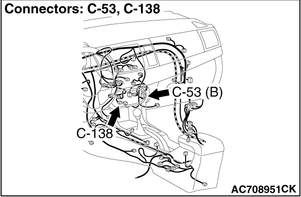
STEP 3. Check heater control panel connector C-138 and heater control
module connector C-53 for loose, corroded or damaged terminals, or terminals pushed back in
the connector.
|
|
|
Q.
Are heater control panel connector C-138 and heater control module connector C-53 in
good condition?
|
|
|
Go to Step 4.
|
|
|
|
|
|
Repair or replace the connector. Refer to GROUP 00E, Harness Connector Inspection .
|
|
|
|
|
|
STEP 4. Check the wiring harness between heater control module connector
C-53 (terminal 9) and heater control panel connector C-138 (terminal 9).
|
|
|
- Check the heater control panel signal line and ground line for open and short
circuit.
|
|
|
Q.
Is the wiring harness between heater control module connector C-53 (terminal 9) and
heater control panel connector C-138 (terminal 9) in good condition?
|
|
|
Go to Step 5.
|
|
|
|
|
|
Repair the wiring harness.
|
|
|
|
|
|
STEP 5. Recheck for diagnostic trouble code.
|
|
|
Recheck if the DTC is set.
|
|
|
(2)Turn the ignition switch to "ON" position.
|
|
|
(3)Check if the DTC is set.
|
|
|
Replace the heater control panel. Then go to Step 6.
|
|
|
|
|
|
It can be assumed that this malfunction is intermittent. Refer to GROUP 00, How
to Use Troubleshooting/Inspection Service Points - How to Cope with Intermittent
Malfunctions .
|
|
|
|
|
|
STEP 6. Recheck for diagnostic trouble code.
|
|
|
Recheck if the DTC is set.
|
|
|
(2)Turn the ignition switch to "ON" position.
|
|
|
(3)Check if the DTC is set.
|
|
|
Replace the heater control module.
|
|
|
|
|
|
It can be assumed that this malfunction is intermittent. Refer to GROUP 00, How
to Use Troubleshooting/Inspection Service Points - How to Cope with Intermittent
Malfunctions .
|
|
|
|
)
)
)