|
|
Required Special Tools:
- MB991223: Harness Set
- MB992006: Extra Fine Probe
|
|
|
Q.
Is ETACS-ECU connector C-317 in good condition?
|
|
|
 Repair or replace the damaged component(s) (Refer to GROUP 00E, Harness Connector Inspection Repair or replace the damaged component(s) (Refer to GROUP 00E, Harness Connector Inspection  ). Check that the input signal of ignition switch (IG1) is normal. ). Check that the input signal of ignition switch (IG1) is normal.
|
|
|
|
|
|
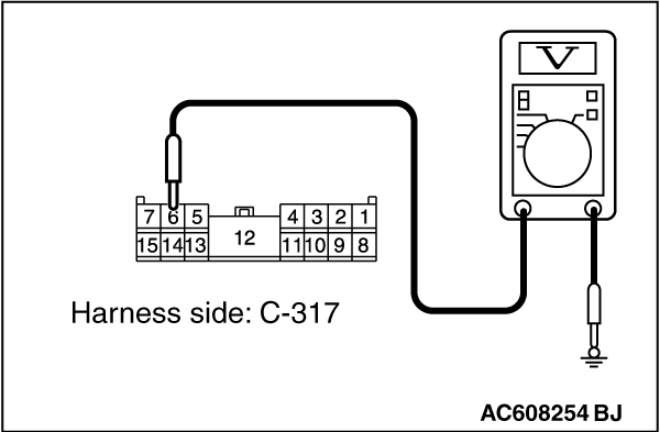
(1)Disconnect ETACS-ECU connector C-317 and measure the voltage available at the junction block side of the connector.
|
|
|
(2)Turn the ignition switch to the "ON" position.
|
|
(3)Measure the voltage between terminal 6 and ground.
- The voltage should measure approximately 12 volts (battery positive voltage).
Q.
Is the measured voltage approximately 12 volts (battery positive voltage)?
 Go to Step 5. Go to Step 5.
Go to Step 3.
|
|
|
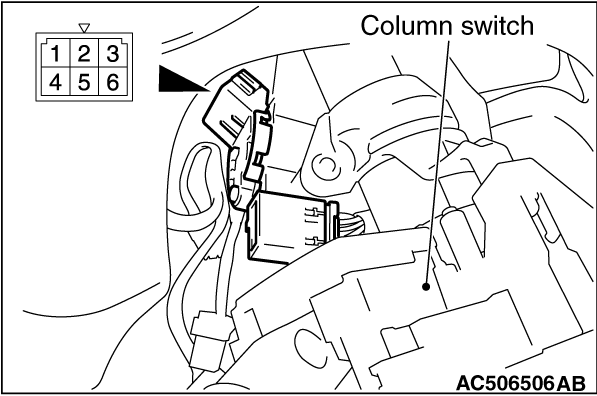
Remove the ignition switch. Then check continuity between the switch terminal.
|
|
|
|
Ignition key position
|
Terminal number
|
Normal condition
|
LOCK
|
1 - 2, 1 - 4, 1 - 5, 1 - 6
|
No continuity
|
ACC
|
1 - 6
|
Continuity exists (2 ohms or less)
|
ON
|
1 - 2 - 4 - 6
|
Continuity exists (2 ohms or less)
|
START
|
1 - 2 - 5
|
Continuity exists (2 ohms or less)
|
|
Q.
Is the ignition switch in good condition?
Go to Step 4.
Replace the ignition switch. Check that the input signal of ignition switch (IG1) is normal.
|
|
|
Check the power supply line (IG1) for open circuit and short circuit.
|
|
|
Q.
Is the wiring harness between ETACS-ECU connector C-317 (terminal 6) and ignition switch (IG1) in good condition?
|
|
|
The wiring harness may be damaged or the connector(s) may have loose, corroded or damaged terminals, or terminals pushed back in the connector. Repair the wiring harness as necessary. Check that the input signal of ignition switch (IG1) is normal.
|
|
|
|
|
|
OK: Normal condition is displayed.
|
|
|
Q.
Is the check result normal?
|
|
|
The trouble can be an intermittent malfunction (Refer to GROUP 00 - How to use Troubleshooting/inspection Service Points, How to Cope with Intermittent Malfunction ).
|
|
|
|
|
|
Refer to Inspection Procedure 2 "Defective power supply system of the ignition switch"
|
|
|
|
![[Previous]](../../../buttons/fprev.png)
![[Next]](../../../buttons/fnext.png)
)
)
)
)