![[Previous]](../../../buttons/fprev.png)
![[Next]](../../../buttons/fnext.png)
DTC B1B7A: Passenger
Seat Weight Sensor (power supply side) Short-circuited or Open (front: LH)
DTC B1B7F:
Passenger Seat Weight Sensor (power supply side) Short-circuited or Open (front: RH)
DTC
B1B84: Passenger Seat Weight Sensor (power supply side) Short-circuited or Open (rear: LH)
DTC
B1B89: Passenger Seat Weight Sensor (power supply side) Short-circuited or Open (rear: RH)
| caution |
If DTC B1B7A, B1B7F, B1B84 or B1B89 is set in the occupant
classification-ECU, always diagnose the CAN main bus lines.
|
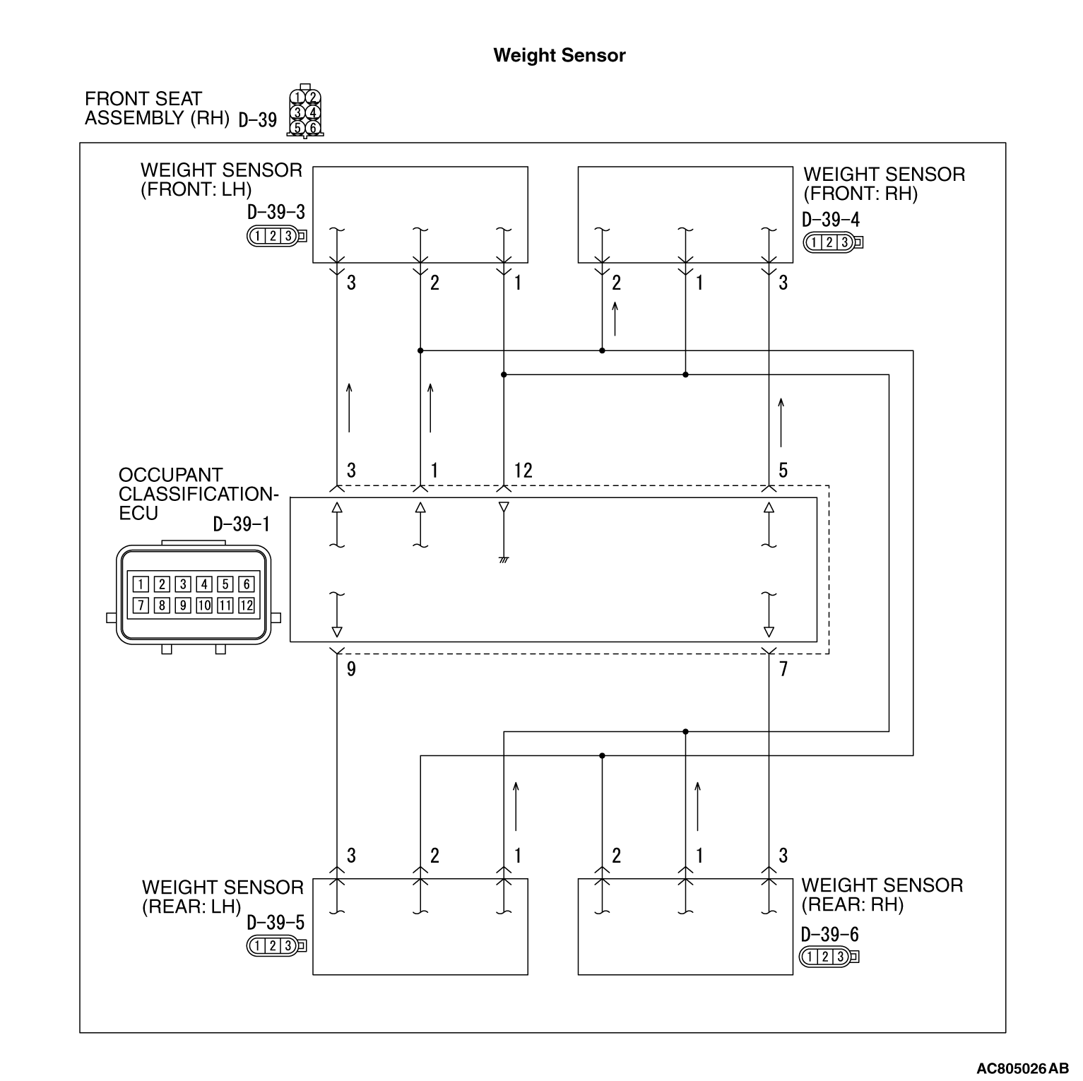
CIRCUIT OPERATION
The load data from the weight sensor is classified with the occupant classification-ECU,
and its classified information is send to SRS-ECU by CAN bus line. The SRS-ECU determines the
air bag deployment based on this classified information, and controls the power supply circuit
to the inflator.
DTC SET CONDITIONS
- This DTC is set if the weight sensor wires are short-circuited
to the power supply.
- This DTC is set if the weight sensor wire are open circuit
|
|
- Damaged wiring harnesses or connectors
- Short to the power supply in the weight sensor harness
- Open circuit in the weight sensor harness
- Malfunction of the weight sensor
- Malfunction of occupant classification-ECU
|
|
|
Required Special Tools:
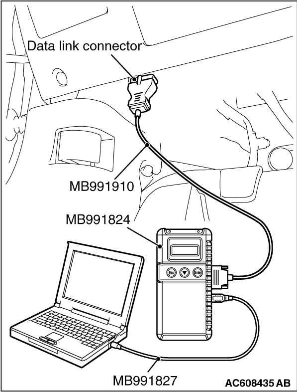
- MB991958: Scan Tool (M.U.T.-III Sub Assembly)
- MB991824: Vehicle Communication Interface (V.C.I.)
- MB991827: M.U.T.-III USB Cable
- MB991910: M.U.T.-III Main Harness A (Vehicles with CAN communication system)
|
|
|
STEP 1. Using scan tool MB991958, diagnose the CAN bus line.
|
|
|
| caution |
To prevent damage to scan tool MB991958, always turn the ignition
switch to the "LOCK" (OFF) position before connecting or disconnecting scan tool MB991958.
|
|
|
(1)Connect scan tool MB991958. Refer to "How to connect the scan tool  ." ."
(2)Turn the ignition switch to the "ON" position.
(3)Diagnose the CAN bus line.
(4)Turn the ignition switch to the "LOCK" (OFF) position.
Q.
Is the CAN bus line found to be normal?
 Go to Step 2. Go to Step 2.
 Repair the CAN bus line (Refer to GROUP 54C, Diagnosis ). Repair the CAN bus line (Refer to GROUP 54C, Diagnosis ).
|
|
|
STEP 2. Recheck for diagnostic trouble code.
|
|
|
Check again if the DTC is set.
|
|
|
(2)Turn the ignition switch to the "ON" position.
|
|
|
(3)Check if the DTC is set.
|
|
|
(4)Turn the ignition switch to the "LOCK" (OFF) position.
|
|
|
Go to Step 3.
|
|
|
|
|
|
There is an intermittent malfunction such as poor engaged connector(s) or open
circuit (Refer to GROUP 00, How to Cope with Intermittent Malfunction ).
|
|
|
|
|
|
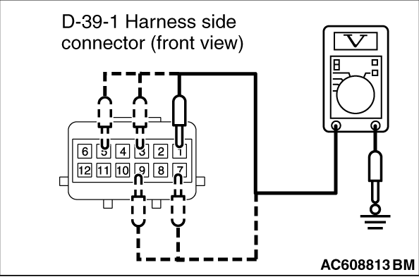
STEP 3. Measure the voltage at occupant classification-ECU connector
D-39-1.
|
|
|
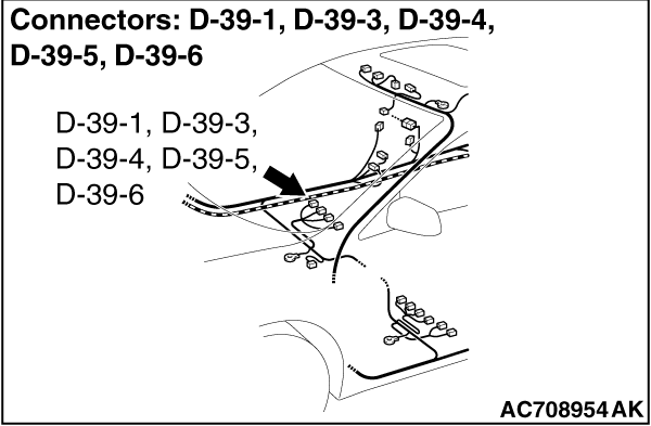
(1)Disconnect the connector D-39-1.
|
|
|
(2)Disconnect weight sensor connector D-39-3, D-39-4, D-39-5 or D-39-6.
|
|
|
(3)Turn the ignition switch to the "ON" position.
|
|
(4)Measure the voltage between terminals 1, 3, 5, 7, 9 and body ground.
Voltage should measure 1 volt or less.
Q.
Is the measured voltage with in the specified range?
Go to Step 4.
Repair the wiring harness between occupant classification-ECU connector D-39-1
terminals 3, 5, 9, 7 and weight sensor connector D-39-3, 4, 5, 6 terminals 3 (signal line) or
occupant classification-ECU connector D-39-1 terminals 1 and weight sensor connector D-39-3
terminals 2 (power supply line). Then go to Step 4.
|
|
|
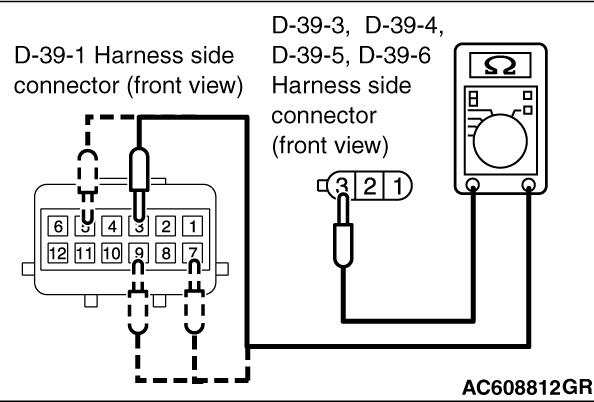
STEP 4. Check the harness open circuit between occupant classification-ECU
connector D-39-1 and weight sensor connector D-39-3, D-39-4, D-39-5 or D-39-6.
|
|
(1)Disconnect occupant classification-ECU connector D-39-1 and weight sensor connector D-39-3,
D-39-4, D-39-5 or D-39-6.
(2)Check for continuity between the following terminals.
It should be less than 2 ohms.
- Occupant classification-ECU connector D-39-1 (terminal No.3)
and the weight sensor connector D-39-3 (terminal No.3)
- Occupant classification-ECU connector D-39-1 (terminal No.5) and the weight sensor
connector D-39-4 (terminal No.3)
- Occupant classification-ECU connector D-39-1 (terminal No.7) and the weight sensor
connector D-39-6 (terminal No.3)
- Occupant classification-ECU connector D-39-1 (terminal No.9) and the weight sensor
connector D-39-5 (terminal No.3)
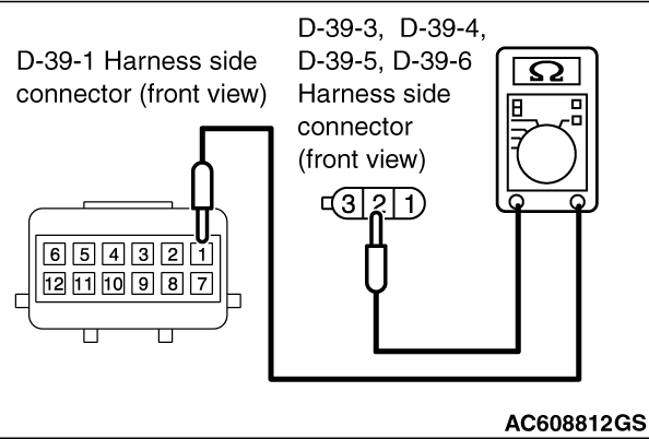
- Occupant classification-ECU connector D-39-1 (terminal No.1) and the weight sensor
connector D-39-3, D-39-4, D-39-5 and D-39-6 (terminal No.2)
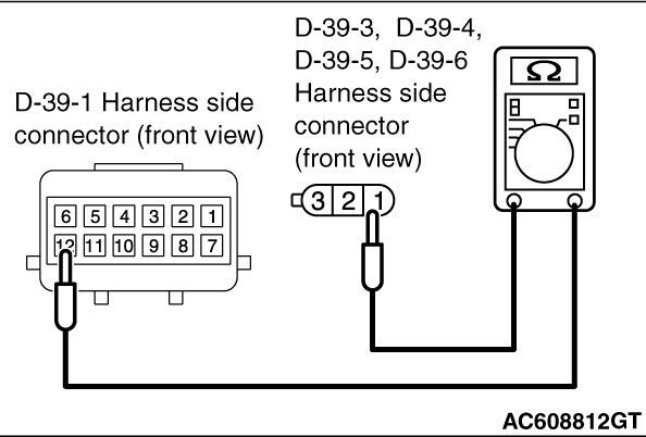
- Occupant classification-ECU connector D-39-1 (terminal No.12) and weight sensor
connector D-39-3, D-39-4, D-39-5 and D-39-6 (terminal No.1)
Q.
Does continuity exist?
Go to Step 5.
Repair the harness wires between occupant classification-ECU connector D-39-1
and weight sensor connector D-39-3, D-39-4, D-39-5 and D-39-6. Then go to Step 5.
|
|
|
STEP 5. Recheck for diagnostic trouble code.
|
|
|
Check again if the DTC is set.
|
|
|
(2)Turn the ignition switch to the "ON" position.
|
|
|
(3)Check if the DTC is set.
|
|
|
(4)Turn the ignition switch to the "LOCK" (OFF) position.
|
|
|
Q.
Is DTCs B1B7A, B1B7F, B1B84, B1B89 set?
|
|
|
Replace the slide adjuster (RH) (Refer to GROUP 52A, Front Seat Assembly ).
|
|
|
|
|
|
There is an intermittent malfunction such as poor engaged connector(s) or open
circuit (Refer to GROUP 00, How to Cope with Intermittent Malfunction ).
|
|
|
|
)
)
)
)
)
)
)