|
|
Required Special Tools:
- MB992006: Extra fine probe
- MB991223: Harness set
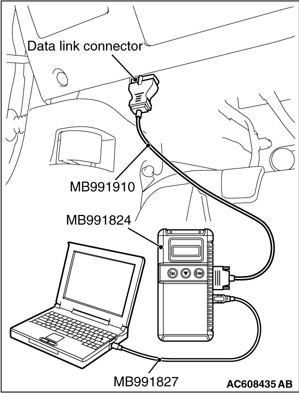
- MB991958 Scan Tool (M.U.T.-III Sub Assembly)
- MB991824: Vehicles Communication Interface (V.C.I.)
- MB991827 M.U.T.-III USB Cable
- MB991910 M.U.T.-III Main Harness A
|
|
(1)
| caution |
To prevent damage to scan tool MB991958, always turn the ignition switch to the "LOCK" (OFF) position before connecting or disconnecting scan tool MB991958.
|
Connect scan tool MB991958. Refer to "How to connect scan tool (M.U.T.-III)  ." ."
(2)Turn the ignition switch to the "ON" position.
(3)Diagnose the CAN bus line.
(4)Turn the ignition switch to the "LOCK" (OFF) position.
Q.
Is the CAN bus line found to be normal?
 Go to Step 2. Go to Step 2.
 Repair the CAN bus line (Refer to GROUP 54C, Diagnosis ). Repair the CAN bus line (Refer to GROUP 54C, Diagnosis ).
|
|
(1)
| caution |
To prevent damage to scan tool MB991958, always turn the ignition switch to the "LOCK" (OFF) position before connecting or disconnecting scan tool MB991958.
|
Connect scan tool MB991958. Refer to "How to connect scan tool (M.U.T.-III) ."
(2)Turn the ignition switch to the "ON" position.
(3)Check whether the KOS-ECU related DTC is set.
(4)Turn the ignition switch to the "LOCK" (OFF) position.
Q.
Is the DTC set?
Diagnose the KOS-ECU. Refer to .
Go to Step 3.
|
|
|
With the ignition switch in the LOCK (OFF) position, check if the following function operates normally:
|
|
|
- Headlights
- Hazard warning light
|
|
|
Q.
Is the check result normal?
|
|
|
Refer to GROUP 54A - Malfunction of ETACS-ECU power supply circuit .
|
|
|
|
|
|
Check that the central door locking system works normally.
|
|
|
Q.
Is the check result normal?
|
|
|
Refer to GROUP 42A - Troubleshooting .
|
|
|
|
|
|
Check the signals related to the keyless entry system operation.
|
|
(1)
| caution |
To prevent damage to scan tool MB991958, always turn the ignition switch to the "LOCK" (OFF) position before connecting or disconnecting scan tool MB991958.
|
Connect scan tool MB991958. Refer to "How to connect the Scan Tool (M.U.T.-III) ."
(2)Turn the ignition switch to the "LOCK" (OFF) position.
(3)Check the ETACS data list.
- Close the driver’s door.
- Close the passenger’s door.
- Close the RH-side rear door.
- Close the LH-side rear door.
- Close the trunk lid.
- Remove the ignition key from the ignition key cylinder.
|
|
Item No.
|
Item name
|
Normal condition
|
Item 256
|
Dr door ajar switch
|
Close
|
Item 257
|
As door ajar switch
|
Close
|
Item 258
|
RR door ajar switch
|
Close
|
Item 259
|
RL door ajar switch
|
Close
|
Item 260
|
Trunk/gate trunk ajar switch
|
Close
|
Item 264
|
Handle lock switch
|
Key in → Key out
|
|
OK: Normal condition are displayed.
Q.
Are the check result normal?
YES <Normal conditions are displayed for all the items.> : Go to Step 6. : Go to Step 6.
NO <Normal condition is not displayed for item No. 256.> : Refer to GROUP 54A, Inspection Procedure 5: ETACS-ECU does not receive any signal from the front door switch (LH) .
NO <Normal condition is not displayed for item No. 257.> : Refer to GROUP 54A, Inspection Procedure 6: ETACS-ECU does not receive any signal from the front door switch (RH) .
NO <Normal condition is not displayed for item No. 258.> : Refer to GROUP 54A, Inspection Procedure 8: ETACS-ECU does not receive any signal from the rear door switch (RH) .
NO <Normal condition is not displayed for item No. 259.> : Refer to GROUP 54A, Inspection Procedure 7: ETACS-ECU does not receive any signal from the rear door switch (LH) .
NO <Normal condition is not displayed for item No. 260.> : Refer to GROUP 54A, Inspection Procedure 9: ETACS-ECU does not receive any signal from the trunk lid latch. .
NO <Normal condition is not displayed for item No. 264.> : Refer to GROUP 54A, Inspection Procedure 3: ETACS-ECU does not receive any signal from the key reminder switch. .
|
|
|
Q.
Are KOS-ECU connector C-05 and receiver antenna assembly connector D-14 in good condition?
|
|
|
Repair or replace the damaged component(s). Refer to GROUP 00E, Harness Connector Inspection . Check that the keyless entry system works normally.
|
|
|
|
|
|
- Check the communication and ground lines for open circuit or short circuit.
|
|
|
Q.
Are the wiring harness between KOS-ECU connector C-05 (terminal Nos. 7, 9, 12, 13 and 32) and receiver antenna assembly connector D-14 (terminal Nos. 12, 3, 1, 5 and 8) in good condition?
|
|
|
The wiring harness may be damaged or the connector(s) may have loose, corroded or damaged terminals, or terminals pushed back in the connector. Repair the wiring harness as necessary. Check that the keyless entry system works normally.
|
|
|
|
|
|
Check that the keyless entry function can be used with another keyless operation key.
|
|
|
Q.
Can the keyless entry function be used?
|
|
|
Replace the keyless operation key concerned and register the ID codes (Refer to ).
|
|
|
|
|
|
Replace receiver antenna assembly. After the replacement, perform the coding, and check that the keyless entry system operates normally.
|
|
|
Q.
Is the check result normal?
|
|
|
The diagnosis is complete.
|
|
|
|
|
|
Replace KOS-ECU and register the ID codes (Refer to ).
|
|
|
|
![[Previous]](../../../buttons/fprev.png)
![[Next]](../../../buttons/fnext.png)
)
)
)
)
)