![[Previous]](../../../buttons/fprev.png)
![[Next]](../../../buttons/fnext.png)
DTC
B2402: STL unit comm.(system ID)
DTC B2403: STL unit comm.(CRC)
DTC B2404:
STL unit comm.(function code)
DTC B2405: STL unit comm.(rolling code)
DTC
B2406: STL unit comm.(PTC operate)
DTC B2407: STL unit comm.(EEPROM)
DTC B2408:
STL unit comm.(solenoid)
| caution |
- If DTC B2402,
B2403, B2404, B2405, B2406, B2407, or B2408 is set, diagnose the CAN bus lines.
- Whenever the steering lock unit is replaced, ensure that the communication circuit
is normal.
|
DTC SET CONDITION
When the ignition push switch is pressed, the steering lock unit communicates with KOS-ECU
to unlock the IG knob. However, if there is a failure shown below, the corresponding DTC is
set.
- B2402: System ID (vehicle specific code) failure
- B2403: Cyclic Redundancy Check (CRC): The error detection strategy to detect a continuously occurring
error (burst error), the calculation result discrepancy
- B2404: Function code failure
- B2405: Rolling code (automatically changing a code for lock/unlock each
time when a lock operation is performed)
- B2406: PTC thermistor continuously activated or activated to prevent solenoid abnormal
heating on the communication with steering lock unit
- B2407: EEPROM failure
- B2408: Communication error between the steering lock unit and KOS-ECU, or solenoid failure
TECHNICAL DESCRIPTION (COMMENT)
Range of check
- When the IG knob unlock communication is performed by pressing the ignition push
switch
Judgment criteria
- B2402: Steering lock unit communication error (system ID) or received system ID
error
- B2403: Steering lock unit communication error (CRC) or received frame CRC calculation
result discrepancy
- B2404: Steering lock unit communication error (function code) or received frame
function code undefined
- B2405: Steering lock unit communication error (rolling code) or received rolling
code out of the permissible range
- B2406: Steering lock unit communication error (PTC operation) or PTC thermistor
activated to prevent solenoid abnormal heating
- B2407: Steering lock unit communication error (EEPROM) or RRPROM failure
- B2408: Steering lock unit communication error (solenoid) or solenoid failure
TROUBLESHOOTING HINTS
- Malfunction of the key reminder switch (integrated into
the steering lock unit)
- Wiring harness or connector failure of CAN bus line
- Malfunction of the KOS-ECU
|
|
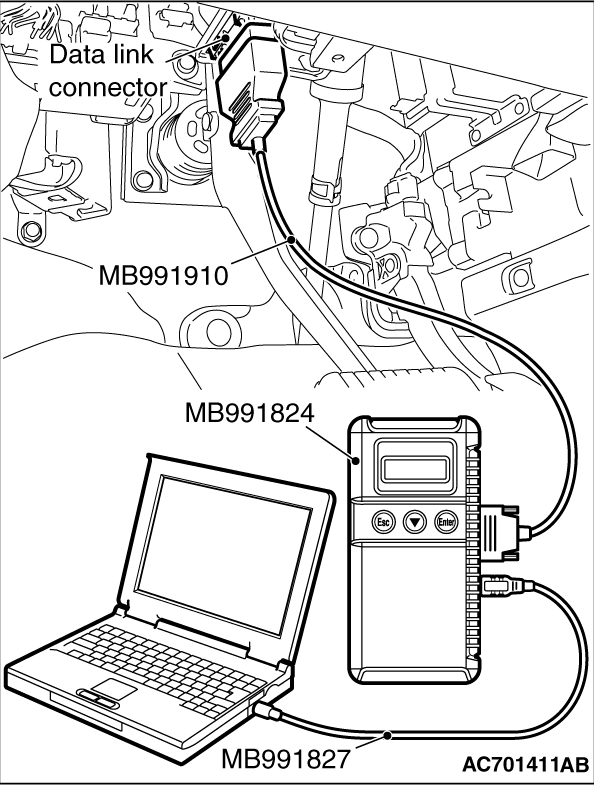
Required Special Tools:
- MB991958 Scan Tool (M.U.T.-III Sub Assembly)
- MB991824: Vehicles Communication Interface (V.C.I.)
- MB991827 M.U.T.-III USB Cable
- MB991910 M.U.T.-III Main Harness A
|
|
|
STEP 1. Using scan tool MB991958, diagnose the CAN bus line.
|
|
(1)
| caution |
To prevent damage to scan tool (MB991958), always turn the ignition switch to the "LOCK"
(OFF) position before connecting or disconnecting scan tool (MB991958).
|
Connect scan tool MB991958 to the data link connector.
(2)Turn the ignition switch to the "ON" position.
(3)Diagnose the CAN bus line.
(4)Turn the ignition switch to the "LOCK" (OFF) position.
Q.
Is the CAN bus line found to be normal?
 Go to Step 2. Go to Step 2.
 Repair the CAN bus line (Refer to GROUP 54C - Diagnosis Repair the CAN bus line (Refer to GROUP 54C - Diagnosis  ). ).
|
|
|
STEP 2. Diagnostic trouble code check
|
|
|
Go to Step 3
|
|
|
|
|
|
Go to Step 6
|
|
|
|
|
|
STEP 3. Check exchange of KOS-ECU
|
|
|
Check whether the KOS-ECU was exchanged.
|
|
|
Q.
Is the check result normal?
|
|
|
Go to Step 4
|
|
|
|
|
|
Go to Step 6
|
|
|
|
|
|
STEP 4. Check exchange of steering lock unit
|
|
|
Check whether the steering lock unit was exchanged.
|
|
|
Q.
Is the check result normal?
|
|
|
Go to Step 6
|
|
|
|
|
|
Go to Step 5
|
|
|
|
|
|
STEP 5. Check registered of steering lock unit
|
|
|
Check whether KOS-ID was registered to the steering lock unit.
|
|
|
Q.
Is the check result normal?
|
|
|
Go to Step 6
|
|
|
|
|
|
Check registration flow chart and register the ID codes (Refer to ).
Then go to Step 10.
|
|
|
|
|
|
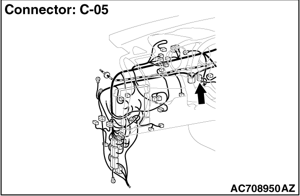
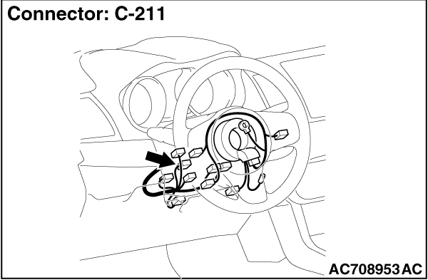
STEP 6. Check key reminder switch connector C-211 and KOS-ECU connector
C-05 for loose, corroded or damaged terminals, or terminals pushed back in the connector.
|
|
|
Q.
Is the key reminder switch connector C-211 and KOS-ECU connector C-05 in good condition?
|
|
|
Go to Step 7.
|
|
|
|
|
|
Repair the defective connector.
|
|
|
|
|
|
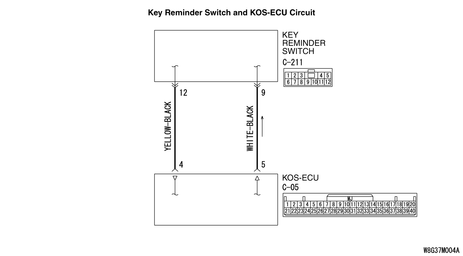
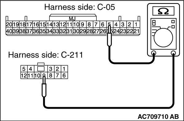
STEP 7. Wiring harness check between C-211 key reminder switch connector
and C-05 KOS-ECU connector for open circuit.
|
|
|
(1)Disconnect C-211 key reminder switch connector and C-05 KOS-ECU connector.
|
|
|
(2)Measure at the connector side of C-211 key reminder switch connector and C-05 KOS-ECU
connector.
|
|
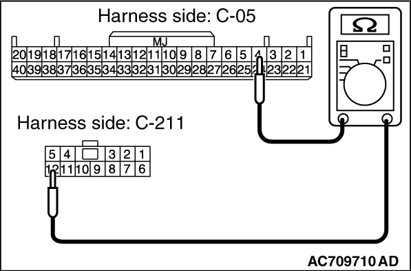
(3)Measure the resistance between the terminals.
- C-211 key reminder switch connector terminal No.9 - C-05 KOS-ECU connector terminal
No.5.
- C-211 key reminder switch connector terminal No.12 - C-05 KOS-ECU connector terminal
No.4.
OK: Continuity exists (2Ω or less)
Q.
Is the check result normal?
Go to Step 8.
NO (C-211 key reminder switch connector terminal No.9 - C-05 KOS-ECU connector
terminal No.5.) : An open circuit is present in the wiring harness between C-211 key reminder switch
connector terminal No. 9 and C-05 KOS-ECU connector terminal No. 5. Repair the wiring harness.
NO (C-211 key reminder switch connector terminal No.12 - C-05 KOS-ECU connector
terminal No.4.) : An open circuit is present in the wiring harness between C-211 key reminder switch
connector terminal No. 12 and C-05 KOS-ECU connector terminal No. 4. Repair the wiring harness.
|
|
|
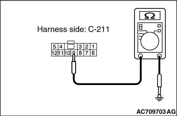
STEP 8. Check the wiring harness between the C-211 key reminder switch
connector (terminal Nos. 9, 12) and the ground for short circuit.
|
|
|
(1)Disconnect C-211 key reminder switch connector, and check the wiring harness.
|
|
(2)Check the wiring harness between C-211 key reminder switch connector (terminal No.9) and
ground
OK: No Continuity
|
|
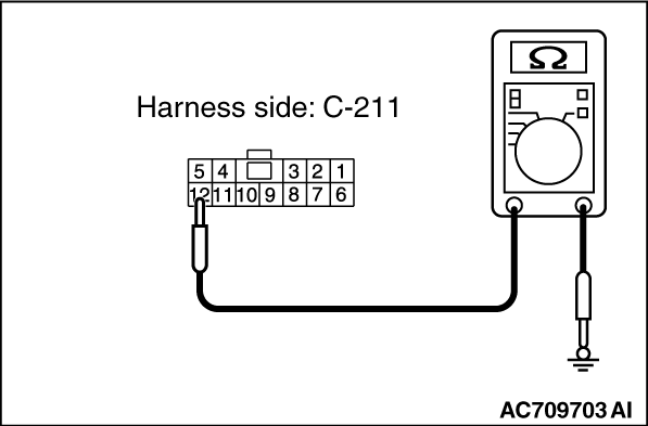
(3)Check the wiring harness between C-211 key reminder switch connector (terminal No.12)
and ground
OK: No Continuity
Q.
Is the wiring harness between C-211 key reminder switch connector (terminal No. 9,
12) and the ground in good condition?
YES  : Go to Step 9. : Go to Step 9.
NO (key reminder switch connector C-211 terminal No.9 - ground.) : Repair the wiring harness between C-211 key reminder switch connector (terminal
No. 9) and the ground.
NO (key reminder switch connector C-211 terminal No.12 - ground.) : Repair the wiring harness C-211 key reminder switch connector (terminal No. 12)
and the ground.
|
|
|
STEP 9. Replace the key reminder switch, and check whether the diagnostic
trouble code is reset.
|
|
|
(2)Turn the ignition switch from the "LOCK" (OFF) position to the "ON" position.
|
|
|
(3)Check if the DTC is set.
|
|
|
Replace KOS-ECU and register the ID codes (Refer to ).
|
|
|
|
|
|
The trouble can be an intermittent malfunction (Refer to GROUP 00 - How
to use Troubleshooting/inspection Service Points - How to Cope with Intermittent
Malfunction ).
|
|
|
|
|
|
STEP 10. Check whether the diagnostic trouble code is reset.
|
|
|
(2)Turn the ignition switch from the "LOCK" (OFF) position to the "ON" position.
|
|
|
(3)Check if the DTC is set.
|
|
|
Replace KOS-ECU and register the ID codes. (Refer to .)
|
|
|
|
|
|
The procedure is complete.
|
|
|
|
)
)
)
)
)
)
)
)