|
|
- The wheel cylinder pressure sensor is integrated into the hydraulic unit. It converts the signal of brake fluid pressure in wheel cylinder of each wheel to the voltage value, then outputs the value to ASC-ECU.
- The wheel cylinder pressure sensor contains the following two signal output sections: Fluid pressure signal output section and fluid pressure and temperature signal output section.
|
|
|
This diagnostic trouble codes will be set under the cases below:
|
|
|
- The pressure sensor offset is outside the specified range. (Pressure is generated at all times)
- The estimated pressure sensor temperature is not normal.
|
|
|
- Damaged wiring harness and connectors
- Incorrect adjustment of brake pedal height
- Master cylinder malfunction
- Brake booster malfunction
- Incorrect installation position of stoplight switch
- Malfunction of the stoplight switch
- Brake drag
- Malfunction of the ASC-ECU
|
|
|
Required Special Tools:
- MB991958 Scan Tool (M.U.T.-III Sub Assembly)
- MB991824: Vehicle Communication Interface (V.C.I.)
- MB991827 M.U.T.-III USB Cable
- MB991910 M.U.T.-III Main Harness A
- MB991997: ASC check harness
|
|
|
Using scan tool MB991958, diagnose the CAN bus lines.
|
|
|
Q.
Is the check result normal?
|
|
|
 Repair the CAN bus lines. (Refer to GROUP 54C - Troubleshooting Repair the CAN bus lines. (Refer to GROUP 54C - Troubleshooting  .) After repairing the CAN bus line, go to Step 2. .) After repairing the CAN bus line, go to Step 2.
|
|
|
|
|
|
This diagnosis is complete.
|
|
|
|
|
|
Check if the diagnostic trouble code No. C121E is set in ASC-ECU.
|
|
|
Q.
Is the check result normal?
|
|
|
Carry out the diagnosis for the diagnostic trouble code No. C121E. (Refer to .)
|
|
|
|
|
|
Check the following service data. (Refer to .)
|
|
|
- Item 129: FL wheel cylinder pressure
- Item 130: FR wheel cylinder pressure
- Item 131: RL wheel cylinder pressure
- Item 132: RR wheel cylinder pressure
|
|
|
Q.
Is the check result normal?
|
|
|
Check the brake drag force. (Refer to GROUP 35A - On-vehicle Service .)
|
|
|
Q.
Is the check result normal?
|
|
|
Adjust the brake drag, and then go to Step 11.
|
|
|
|
|
|
Refer to GROUP 35A - On-vehicle Service .
|
|
|
Q.
Is the check result normal?
|
|
|
Adjust the brake pedal height to the standard value. (Refer to GROUP 35A - On-vehicle Service .) Then go to Step 11.
|
|
|
|
|
|
Refer to GROUP 35A - On-vehicle Service .
|
|
|
Q.
Is the check result normal?
|
|
|
Install the stoplight switch correctly. (Refer to GROUP 35A - On-vehicle Service .) Then go to Step 11.
|
|
|
|
|
|
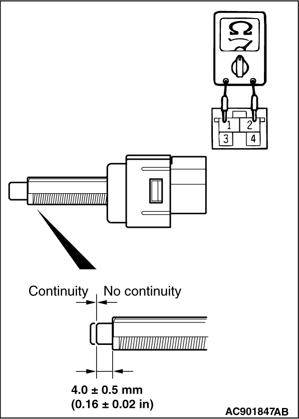
(1)Remove the stoplight switch. (Refer to GROUP 35A - Brake Pedal .)
|
|
(2)Connect the circuit tester (Ω range) to the stoplight switch connector terminal Nos. 1 and 2.
(3)When continuity does not exist with the plunger pressed from the outer case end face by the dimension shown in the figure, and when continuity exists with the plunger released, the switch is in good condition.
Q.
Is the check result normal?
 Go to Step 9. Go to Step 9.
Replace the stoplight switch. (Refer to GROUP 35A - Brake Pedal .) Then go to Step 11.
|
|
|
Refer to GROUP 35A - On-vehicle Service .
|
|
|
Q.
Is the check result normal?
|
|
|
Replace the brake booster. (Refer to GROUP 35A - Master Cylinder Assembly and Brake Booster .) Then go to Step 11.
|
|
|
|
|
|
Replace the hydraulic unit (incorporates in ASC-ECU).(Refer to .) Then go to Step 11.
|
|
|
|
|
|
Intermittent malfunction. (Refer to GROUP 00 - How to Cope with Intermittent Malfunction .)
|
|
|
|
|
|
The procedure is complete.
|
|
|
|
![[Previous]](../../../buttons/fprev.png)
![[Next]](../../../buttons/fnext.png)
)