![[Previous]](../../../buttons/fprev.png)
![[Next]](../../../buttons/fnext.png)
DTC C2204: Internal
abnormality in G and yaw rate sensor
|
|
| caution |
- If there is any problem in the
CAN bus lines, an incorrect diagnostic trouble code may be set. Prior to this diagnosis, diagnose
the CAN bus lines.
- Whenever the ECU is replaced, ensure that the CAN bus lines are normal.
- Do not drop the G and yaw rate sensor or subject it to a shock.
- When the G and yaw rate sensor is replaced, always perform the calibration to make
ASC-ECU learn the neutral point. (Refer to
 .) .)
- When the hydraulic unit (integrated with ASC-ECU) is replaced, always perform the
calibration of steering wheel sensor, G and yaw rate sensor, brake fluid pressure sensor, cut
valve, and inlet valve.(Refer to , , ,
and .)
|
|
|
|
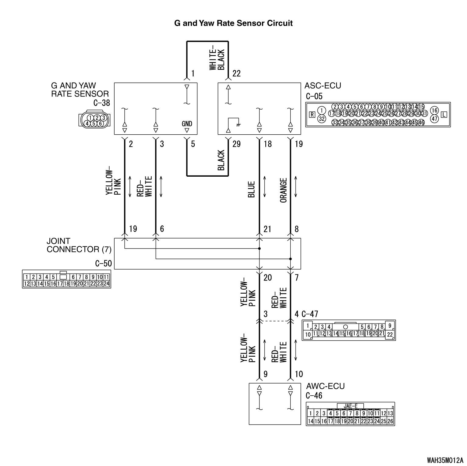
- ASC-ECU supplies power to the G and yaw rate sensor at the terminal No. 1.
- The G and yaw rate sensor outputs the signal to ASC-ECU via the local CAN bus lines.
|
|
|
This diagnostic trouble code is set if any malfunction below is found:
|
|
|
- Abnormality is detected by the self-diagnosis of the
G and yaw rate sensor.
- Output value of the G and yaw rate sensor is not within the standard value range.
|
|
|
| note |
This diagnostic trouble code may be set when G and yaw rate sensor is put on the turntable
turning at high speed.
|
|
|
|
- Improper installation of the G and yaw rate sensor
- Damaged wiring harness and connectors
- G and yaw rate sensor malfunction
- ASC-ECU malfunction
|
|
|
Required Special Tools:
- MB991958 Scan Tool (M.U.T.-III Sub Assembly)
- MB991824: Vehicle Communication Interface (V.C.I.)
- MB991827 M.U.T.-III USB Cable
- MB991910 M.U.T.-III Main Harness A
|
|
|
STEP 1. Using scan tool MB991958, diagnose the CAN bus lines.
|
|
|
Using scan tool MB991958, diagnose the CAN bus lines.
|
|
|
Q.
Is the check result normal?
|
|
|
 Go to Step 2. Go to Step 2.
|
|
|
|
|
|
 Repair the CAN bus lines. (Refer to GROUP 54C - Troubleshooting .)
After repairing the CAN bus line, go to Step 2. Repair the CAN bus lines. (Refer to GROUP 54C - Troubleshooting .)
After repairing the CAN bus line, go to Step 2.
|
|
|
|
|
|
STEP 2. Check for diagnostic trouble codes of other systems
|
|
|
Check if diagnostic trouble code No. U0125 is also set in ASC-ECU.
|
|
|
Perform troubleshooting for the DTC that is set. (Refer to .)
Then go to Step 3.
|
|
|
|
|
|
Go to Step 3.
|
|
|
|
|
|
STEP 3. Check whether the DTC is reset.
|
|
|
Go to Step 4.
|
|
|
|
|
|
The procedure is complete.
|
|
|
|
|
|
STEP 4. Scan tool service data
|
|
|
Check the following service data. (Refer to .)
|
|
|
- Item 08: Lateral G sensor
- Item 09: G sensor
- Item 12: Yaw rate sensor
- Item 73: Lateral G sensor offset
- Item 97: Yaw rate sensor offset
|
|
|
Q.
Is the check result normal?
|
|
|
Go to Step 8.
|
|
|
|
|
|
Go to Step 5.
|
|
|
|
|
|
STEP 5. G and yaw rate sensor installation check
|
|
|
Check that the G and yaw rate sensor is installed correctly.
|
|
|
Q.
Is the check result normal?
|
|
|
Go to Step 6.
|
|
|
|
|
|
Reinstall the G and yaw rate sensor correctly (Refer to ),
and then go to Step 8.
|
|
|
|
|
|
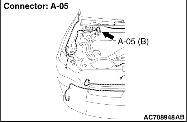
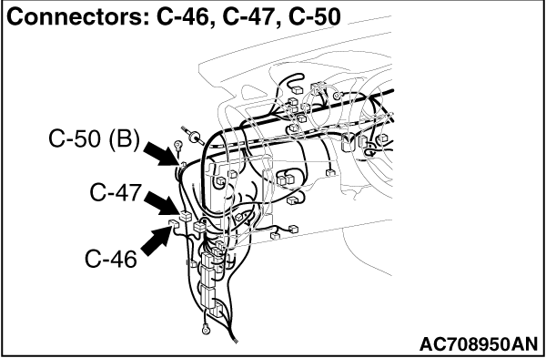
STEP 6. Connector check: A-05 ASC-ECU connector, C-46 AWC-ECU connector,
C-47 intermediate connector, C-50 joint connector
|
|
|
Q.
Is the check result normal?
|
|
|
Go to Step 7.
|
|
|
|
|
|
Repair the connector, and then go to Step 8.
|
|
|
|
|
|
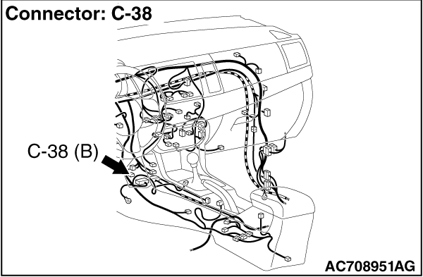
STEP 7. Wiring harness check between A-05 ASC-ECU connector terminal
No. 18 and C-38 G and yaw rate sensor connector terminal No. 2, between A-05 ASC-ECU connector
terminal No. 19 and C-38 G and yaw rate sensor connector terminal No. 3, between C-46 AWC-ECU connector
terminal No. 9 and C-38 G and yaw rate sensor connector terminal No. 2, between C-46 AWC-ECU connector
terminal No. 10 and C-38 G and yaw rate sensor connector terminal No. 3
|
|
|
- Open or short circuit check of communication circuit
|
|
|
Q.
Is the check result normal?
|
|
|
Go to Step 8.
|
|
|
|
|
|
Repair the wiring harness, and then go to Step 8.
|
|
|
|
|
|
STEP 8. Check whether the DTC is reset.
|
|
|
(2)Drive the vehicle at 12mph (20 km/h) or higher.
|
|
|
Replace the G and yaw rate sensor (Refer to ). Then
go to Step 9.
|
|
|
|
|
|
Intermittent malfunction (Refer to GROUP 00 - How to Use Troubleshooting/How
to Cope with Intermittent Malfunctions ).
|
|
|
|
|
|
STEP 9. Check whether the DTC is reset.
|
|
|
(2)Drive the vehicle at 12mph (20 km/h) or higher.
|
|
|
Replace the hydraulic unit (incorporates in ASC-ECU).(Refer to .)
Then, go to Step 10.
|
|
|
|
|
|
Intermittent malfunction (Refer to GROUP 00 - How to Use Troubleshooting/How
to Cope with Intermittent Malfunctions ).
|
|
|
|
|
|
STEP 10. Check whether the DTC is reset.
|
|
|
(2)Drive the vehicle at 12mph (20 km/h) or higher.
|
|
|
Return to Step 1.
|
|
|
|
|
|
The procedure is complete.
|
|
|
|
)
)
)
)