|
|
- Each wheel speed detecting section is a kind of a pulse generator. It consists of the encoder (plate on which the north and south pole of magnet are arranged alternately) for detecting the wheel speed, which rotates at the same speed of the wheels, and the wheel speed sensor. This detecting section outputs the frequency pulse signals in proportion to the wheel speed.
- The pulse signals generated by the wheel speed detecting section are sent to ASC-ECU. ASC-ECU uses the frequency of the pulse signals to determine the wheel speed.
|
|
|
ASC-ECU monitors the electric current in each wheel speed sensor circuit. If an open or short circuit in the wheel speed sensor circuit is detected, ASC-ECU sets a corresponding diagnostic trouble code.
|
|
|
Current trouble
- Damaged wiring harness and connectors
- Noise interference
- Malfunction of wheel speed sensor
- ASC-ECU malfunction
|
|
|
Past trouble
- Carry out the diagnosis with a particular emphasis on the wiring harness and connector failures between ASC-ECU and the wheel speed sensor. For diagnosis procedures, refer to How to Treat Past Trouble (GROUP 00 - How to Use Troubleshooting/Inspection Service Points
 ). ).
|
|
|
Required Special Tools:
- MB991958 Scan Tool (M.U.T.-III Sub Assembly)
- MB991824: Vehicle Communication Interface (V.C.I.)
- MB991827 M.U.T.-III USB Cable
- MB991910 M.U.T.-III Main Harness A
- MB991997: ASC check harness
|
|
|
Using scan tool MB991958, diagnose the CAN bus lines.
|
|
|
Q.
Is the check result normal?
|
|
|
 Repair the CAN bus lines (Refer to GROUP 54C - CAN Bus Diagnostics table ). On completion, go to Step 2. Repair the CAN bus lines (Refer to GROUP 54C - CAN Bus Diagnostics table ). On completion, go to Step 2.
|
|
|
|
|
|
This diagnosis is complete.
|
|
|
|
|
|
Check the following service data. (Refer to .)
|
|
|
- Item No.03: RL wheel speed sensor
|
|
|
Q.
Is the check result normal?
|
|
|
Q.
Is the check result normal?
|
|
|
Repair the defective connector. Then go to Step 11.
|
|
|
|

|
(1)Disconnect the ASC-ECU connector, connect the special tool ASC check harness (MB991997) to the wiring harness-side connector, and then measure at the special tool connector side.
| note |
Do not connect the special tool to ASC-ECU.
|
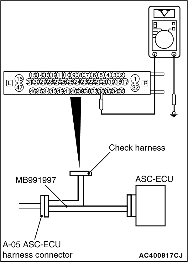
(2)Turn the ignition switch to the ON position.
(3)Measure the voltage between the wheel speed sensor power supply terminal (signal terminal) No. 36 and the body ground as well as between the ground terminal No. 37 and the body ground.
OK: 1 volt or less
Q.
Is the check result normal?
YES  : Go to Step 6. : Go to Step 6.
NO (Not normal at the terminal No. 34 or 33) : Go to Step 8.
|
|
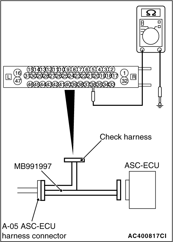
(1)Disconnect the ASC-ECU connector, connect the special tool ASC check harness (MB991997) to the wiring harness-side connector, and then measure at the special tool connector side.
| note |
Do not connect the special tool to ASC-ECU.
|
(2)Measure the resistance between the wheel speed sensor circuit power supply terminal (signal terminal) No. 36 and the body ground as well as between the ground terminal No. 37 and the body ground.
OK: No continuity
Q.
Is the check result normal?
YES : Go to Step 7.
NO (Not normal at the terminal No. 36 or 37) : Go to Step 8.
|
|
(1)Disconnect the ASC-ECU connector, connect special tool ASC check harness (MB991997) to the ASC-ECU-side connector and the wiring harness-side connector, and then measure at the special tool connector side.
(2)Turn the ignition switch to the ON position.
(3)Measure the voltage between the wheel speed sensor circuit power supply terminal (signal terminal) No. 36 and the body ground and between the wheel speed sensor circuit ground terminal No. 37 and the body ground.
OK:
Terminal No.36 and the body ground: Battery positive voltage
Terminal No.37 and the body ground: 1 V or less
Q.
Is the check result normal?
 Go to Step 8. Go to Step 8.
Go to Step 10.
|
|
|
Q.
Is the check result normal?
|
|
|
Replace the wheel speed sensor <RL>. (Refer to .) Then go to Step 11.
|
|
|
|
|
|
- Check for short or open circuit in wheel speed sensor <RL> circuit
|
|
|
Q.
Is the check result normal?
|
|
|
Repair the wiring harness. Then go to Step 11.
|
|
|
|
|
|
(2)Drive the vehicle at 12mph (20 km/h) or more.
| note |
The ABS warning light does not turn OFF in some cases unless the vehicle runs at 12mph (20 km/h) or higher.
|
|
|
|
Replace the hydraulic unit (incorporates in ASC-ECU).(Refer to .) Then go to Step 11.
|
|
|
|
|
|
Intermittent malfunction. (Refer to GROUP 00 - How to Cope with Intermittent Malfunction .)
|
|
|
|
|
|
(2)Drive the vehicle at 12mph (20 km/h) or more.
| note |
The ABS warning light does not turn OFF in some cases unless the vehicle runs at 12mph (20 km/h) or higher.
|
|
|
|
This diagnosis is complete.
|
|
|
|
![[Previous]](../../../buttons/fprev.png)
![[Next]](../../../buttons/fnext.png)
)
)
)
)
)
)
)