![[Previous]](../../../buttons/fprev.png)
![[Next]](../../../buttons/fnext.png)
Inspection Procedure 11: ASC-ECU power supply circuit system

|
|
| caution |
- When the ASC-ECU power supply voltage becomes 9.7 ± 0.3 V or less, the ABS warning light, ASC warning display, and ASC OFF display illuminate, and the ABS, stability control, and TCL controls are prohibited.
- If the battery terminal is not tightened properly, a dump surge may occur and the power supply voltage may become abnormally high for a short period of time.
- If there is any problem in the CAN bus lines, an incorrect diagnostic trouble code may be set. Prior to this diagnosis, diagnose the CAN bus lines.
- Whenever the ECU is replaced, ensure that the CAN bus lines are normal.
- When the hydraulic unit (integrated with ASC-ECU) is replaced, always perform the calibration of steering wheel sensor, G and yaw rate sensor, brake fluid pressure sensor, cut valve, and inlet valve.(Refer to
 , , , and .) , , , and .)
|
|
|
|
- ASC-ECU contains the power supply circuit (terminal No. 32) for the solenoid valve. The solenoid valve is energized by the valve relay, which is incorporated in ASC-ECU.
- ASC-ECU contains the power supply circuit (terminal No. 1) for the pump motor. The pump motor is energized by the motor relay, which is incorporated in ASC-ECU.
- ASC-ECU contains the power supply circuit (terminal No. 2) for ASC-ECU, and the power is supplied from the fusible link No. 34 through the multi-purpose fuse No. 17.
- If a malfunction occurs in the ASC-ECU power supply, the communication with scan tool becomes unavailable.
|
|
|
- Damaged wiring harness and connectors
- Malfunction of fuse or fusible link
- Improper tightening of battery terminal
- Improper tightening of grounding bolt
- Battery failure
- Charging system failed
- ASC-ECU malfunction
|
|
|
Required Special Tools:
- MB991958 Scan Tool (M.U.T.-III Sub Assembly)
- MB991824: Vehicle Communication Interface (V.C.I.)
- MB991827 M.U.T.-III USB Cable
- MB991910 M.U.T.-III Main Harness A
- MB991997: ASC check harness
|
|
|
Refer to GROUP 54A - Battery Test .
|
|
|
Q.
Is the battery in good condition?
|
|
|
 Go to Step 3. Go to Step 3.
|
|
|
|
|
|
 Charge or replace the battery. Then, go to Step 2. Charge or replace the battery. Then, go to Step 2.
|
|
|
|
|
|
STEP 2. Charging system check
|
|
|
Refer to GROUP 16 - Output Current Test .
|
|
|
Q.
Is the charging system in good condition?
|
|
|
Go to Step 3.
|
|
|
|
|
|
Repair or replace the charging system component(s).
|
|
|
|
|
|
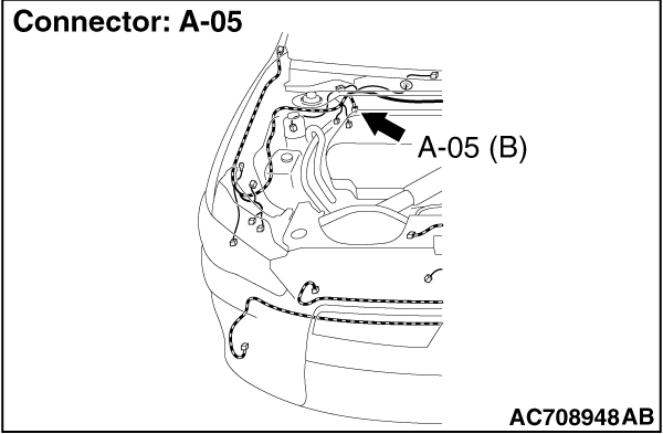
STEP 3. Connector check: A-05 ASC-ECU connector
|
|
|
Q.
Is the check result normal?
|
|
|
Go to Step 4.
|
|
|
|
|
|
NO : Repair the defective connector.
|
|
|
|
|
|
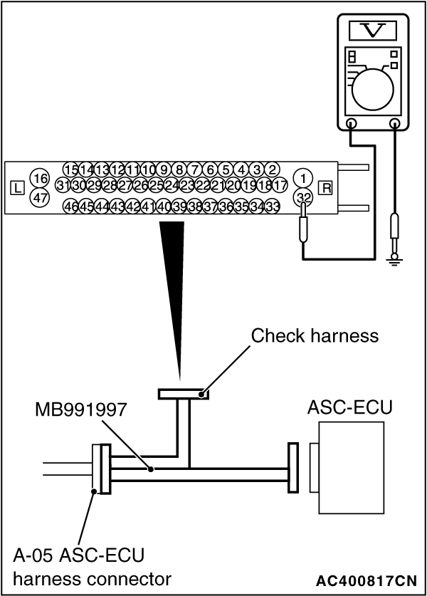
STEP 4. Voltage measurement at A-05 ASC-ECU connector
|
|
(1)Disconnect the connector, connect the ASC check harness (Special tool: MB991997) to the wiring harness-side connector, and measure the voltage at the special tool connector side.
| note |
Do not connect the special tool to ASC-ECU.
|
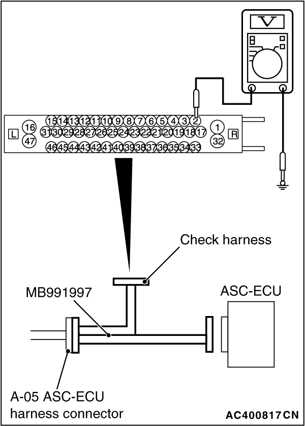
(2)Measure the voltage between the terminal No. 32 and the body ground.
OK: Battery positive voltage
Q.
Is the check result normal?
Go to Step 7.
Go to Step 5.
|
|
|
STEP 5. Fusible link check: Check the fusible link No. 27.
|
|
|
Q.
Is the check result normal?
|
|
|
An open circuit may be present in the power supply circuit. Repair the wiring harness between A-05 ASC-ECU connector terminal No. 32 and the fusible link No. 27.
|
|
|
|
|
|
Go to Step 6.
|
|
|
|
|
|
STEP 6. Wiring harness check between A-05 ASC-ECU connector and fusible link No. 27.
|
|
|
(1)Disconnect ASC-ECU connector A-05.
|
|
|
(2)Remove fusible link No. 27.
|
|
|
(3)Check the continuity (short to ground) between A-05 ASC-ECU connector terminal No. 32 and the ground.
OK: No continuity
|
|
|
Q.
Is the check result normal?
|
|
|
Replace the fusible link No.27.
|
|
|
|
|
|
Short circuit may be present in the power supply circuit. Repair the wiring harness between A-05 ASC-ECU connector terminal No. 32 and fusible link No. 27.
|
|
|
|
|
|
STEP 7. Voltage measurement at A-05 ASC-ECU connector
|
|
(1)Disconnect the connector, connect the ASC check harness (Special tool: MB991997) to the wiring harness-side connector, and measure the voltage at the special tool connector side.
| note |
Do not connect the special tool to ASC-ECU.
|
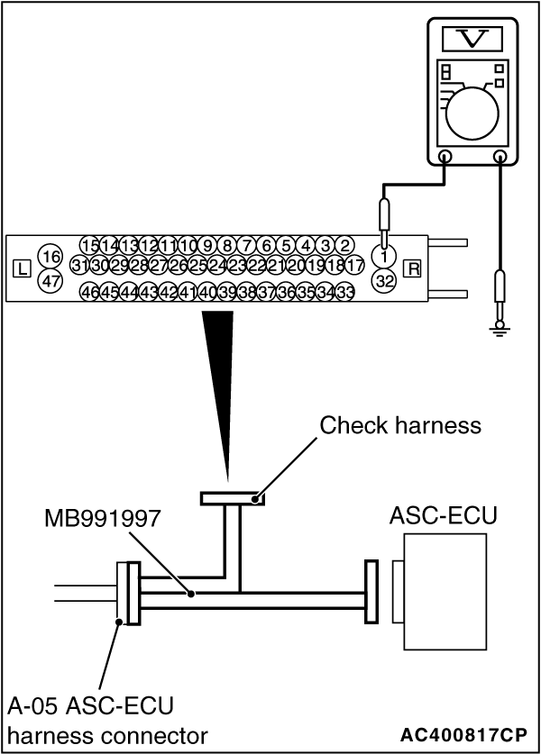
(2)Measure the voltage between the terminal No. 1 and the body ground.
OK: Battery positive voltage
Q.
Is the check result normal?
Go to Step 10.
Go to Step 8.
|
|
|
STEP 8. Fusible link check: Check the fusible link No.26.
|
|
|
Visually check for open circuit in the fusible link No.26.
|
|
|
Q.
Is the check result normal?
|
|
|
An open circuit may be present in the pump motor power supply circuit. Repair the wiring harness between A-05 ASC-ECU connector terminal No. 1 and the fusible link No. 26.
|
|
|
|
|
|
Go to Step 9.
|
|
|
|
|
|
STEP 9. Wiring harness check between A-05 ASC-ECU connector and fusible link No. 26.
|
|
|
(1)Disconnect ASC-ECU connector A-05.
|
|
|
(2)Remove fusible link No. 26.
|
|
|
(3)Check the continuity (short to ground) between A-05 ASC-ECU connector terminal No. 1 and the ground.
OK: No continuity
|
|
|
Q.
Is the check result normal?
|
|
|
Replace the fusible link No.26.
|
|
|
|
|
|
Short circuit may be present in the power supply circuit. Repair the wiring harness between A-05 ASC-ECU connector terminal No. 1 and fusible link No. 26.
|
|
|
|
|
|
STEP 10. Check of fuse No. 17 and fusible link No. 34
|
|
|
Visually check for open circuit in the fuse No. 17 and the fusible link No. 34.
|
|
|
Q.
Is the check result normal?
|
|
|
Go to Step 16.
|
|
|
|
|
|
Go to Step 11.
|
|
|
|
|
|
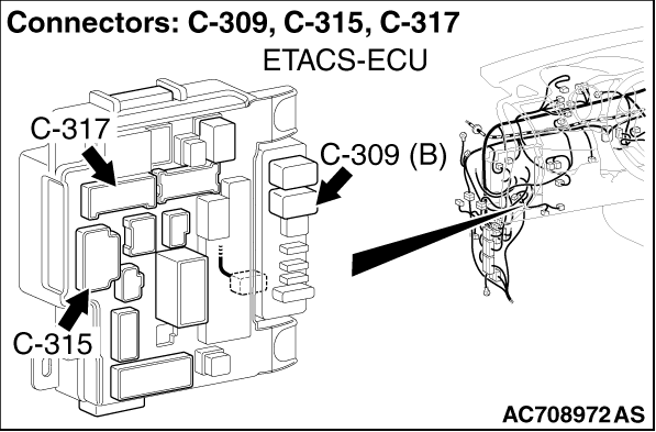
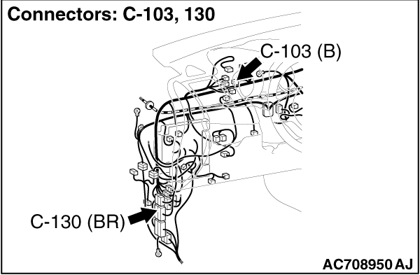
STEP 11. Connector check: C-41 intermediate connector, C-43 joint connector, C-46 ETACS-ECU connector, C-103 joint connector, C-130 intermediate connector, C-309 ETACS-ECU connector and C-315 ETACS-ECU connector
|
|
|
Q.
Is the check result normal?
|
|
|
Go to Step 12.
|
|
|
|
|
|
Repair the connector. Then, replace fuse No. 17 or fusible link No. 34.
|
|
|
|
|
|
STEP 12. Wiring harness check between C-309 ETACS-ECU connector and fusible link No. 34.
|
|
|
(1)Remove fusible link No. 34.
|
|
|
(2)Disconnect ETACS-ECU connector C-309, and measure at the wiring harness side.
|
|
|
(3)Check the continuity (short to ground) between terminal No. 1 and the ground.
OK: No continuity
|
|
|
Q.
Is the check result normal?
|
|
|
Go to Step 13.
|
|
|
|
|
|
Repair the wiring harness between C-309 ETACS-ECU connector terminal No. 1 and fusible link No. 34. Then, replace fuse No. 17 or fusible link No. 34.
|
|
|
|
|
|
STEP 13. Wiring harness check between C-315 ETACS-ECU connector and C-103 joint connector.
|
|
|
(1)Disconnect the C-103 joint connector.
|
|
|
(2)Disconnect ETACS-ECU connector C-315, and measure at the wiring harness side.
|
|
|
(3)Check the continuity (short to ground) between terminal No. 4 and the ground.
OK: No continuity
|
|
|
Q.
Is the check result normal?
|
|
|
Go to Step 14.
|
|
|
|
|
|
Repair the wiring harness between C-315 ETACS-ECU connector terminal No. 4 and C-103 joint connector terminal No.18. Then, replace fuse No. 17 or fusible link No. 34.
|
|
|
|
|
|
STEP 14. Wiring harness check between the C-103 joint connector and the C-46 AWC-ECU connector.
|
|
|
(1)Disconnect the C-46 AWC-ECU connector.
|
|
|
(2)Disconnect the C-103 joint connector, and measure at the wiring harness side.
|
|
|
(3)Check the continuity (short to ground) between terminal No. 16 and the ground.
OK: No continuity
|
|
|
Q.
Is the check result normal?
|
|
|
Go to Step 15.
|
|
|
|
|
|
Repair the wiring harness between C-103 joint connector terminal No.16 and C-46 AWC-ECU connector terminal No.12. Then, replace fuse No. 17 or fusible link No. 34.
|
|
|
|
|
|
STEP 15. Wiring harness check between the C-103 joint connector and the A-05 ASC-ECU connector.
|
|
|
(1)Disconnect ASC-ECU connector A-05.
|
|
|
(2)Disconnect the C-103 joint connector, and measure at the wiring harness side.
|
|
|
(3)Check the continuity (short to ground) between terminal No.17 and the ground.
OK: No continuity
|
|
|
Q.
Is the check result normal?
|
|
|
Replace the fuse No. 17 or the fusible link No. 34. Then, go to Step 20.
|
|
|
|
|
|
Repair the wiring harness between C-103 joint connector terminal No.17 and A-05 ASC-ECU connector terminal No.2. Then, replace fuse No. 17 or fusible link No. 34.
|
|
|
|
|
|
STEP 16. Voltage measurement at A-05 ASC-ECU connector
|
|
(1)Disconnect the connector, connect the ASC check harness (Special tool: MB991997) to the wiring harness-side connector, and measure the voltage at the special tool connector side.
| note |
Do not connect the special tool to ASC-ECU.
|
(2)Measure the voltage between the terminal No. 2 and the body ground.
OK: Battery positive voltage
Q.
Is the check result normal?
Go to Step 20.
Go to Step 17.
|
|
|
STEP 17. Measure the voltage at the C-309 ETACS-ECU connector.
|
|
|
(1)Disconnect the connector, and measure at the wiring harness-side connector.
|
|
|
(2)Measure the voltage between the terminal No. 1 and the body ground.
OK: Battery positive voltage
|
|
|
Q.
Is the check result normal?
|
|
|
Go to Step 18.
|
|
|
|
|
|
Repair the wiring harness between C-309 ETACS-ECU connector terminal No. 1 and the fusible link No. 34.
|
|
|
|
|
|
STEP 18. Measure the voltage at the C-315 ETACS-ECU connector.
|
|
|
(1)Without disconnecting the connector, measure by backprobing.
|
|
|
(2)Measure the voltage between the terminal No. 4 and the body ground.
OK: Battery positive voltage
|
|
|
Q.
Is the check result normal?
|
|
|
Go to Step 20.
|
|
|
|
|
|
Go to Step 19.
|
|
|
|
|
|
STEP 19. Wiring harness check between A-05 ASC-ECU connector terminal No. 2 and C-315 ETACS-ECU connector terminal No. 4
|
|
|
Q.
Is the check result normal?
|
|
|
Go to Step 20.
|
|
|
|
|
|
NO : Repair the wiring harness.
|
|
|
|
|
|
STEP 20. Resistance measurement at A-05 ASC-ECU connector
|
|
(1)Disconnect the connector, connect the ASC check harness (Special tool: MB991997) to the wiring harness-side connector, and measure the voltage at the special tool connector side.
| note |
Do not connect the special tool to ASC-ECU.
|
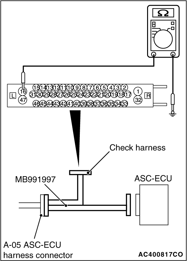
(2)Measure the resistance between the terminal No. 16 and the body ground as well as between the terminal No. 47 and the body ground.
OK: Continuity exists (2 Ω or less)
Q.
Is the check result normal?
Go to Step 21.
NO : Repair the wiring harness.
|
|
|
STEP 21. Retest the system.
|
|
|
Q.
Is the communication with scan tool MB991958 possible?
|
|
|
Intermittent malfunction. (Refer to GROUP 00 - How to Cope with Intermittent Malfunction .)
|
|
|
|
|
|
Check that the scan tool connection cable is properly connected, and that the V.C.I. switch is turned ON. Then, replace the hydraulic unit (integrated with ASC-ECU).(Refer to .) Then go to Step 22.
|
|
|
|
|
|
STEP 22. Retest the system.
|
|
|
Q.
Is the communication with scan tool MB991958 possible?
|
|
|
Return to Step 1.
|
|
|
|
|
|
This diagnosis is complete.
|
|
|
|
)
)
)
)
)
)
)
)