Pre-removal operation
- Engine Room Under Cover Front A, B, Engine Room Under Cover Center and Engine Room Side Cover (RH) Removal (Refer to GROUP 51, Under Cover
 ). ).
- Engine Coolant Draining (Refer to GROUP 14, On-vehicle Service - Engine Coolant Replacement ).
- Engine Oil Draining (Refer to GROUP 12, On-vehicle Service - Engine Oil Replacement ).
- Engine Upper Cover Removal (Refer to GROUP 16, Ignition System - Ignition Coil ).
- Charge Air Cooler Intake Hose A and Charge Air Cooler Intake Pipe A Removal (Refer to ).
- Air Cleaner Assembly and Air Cleaner Intake Hose Removal (Refer to ).
- Front Exhaust Pipe Removal (Refer to ).
- Strut Tower Bar Removal (Refer to GROUP 42A, Strut Tower Bar ).
- Cowl Top Panel Removal (Refer to GROUP 42A, Loose Panel ).
|
Post-installation operation
- Cowl Top Panel Installation (Refer to GROUP 42A, Loose Panel ).
- Strut Tower Bar Installation (Refer to GROUP 42A, Strut Tower Bar ).
- Front Exhaust Pipe Installation (Refer to ).
- Charge Air Cooler Intake Hose A and Charge Air Cooler Intake Pipe A Installation (Refer to ).
- Air Cleaner Assembly and Air Cleaner Intake Hose Installation (Refer to ).
- Engine Oil Refilling (Refer to GROUP 12, On-vehicle Service - Engine Oil Replacement ).
- Engine Coolant Refilling (Refer to GROUP 14, On-vehicle Service - Engine Coolant Replacement ).
- Engine Upper Cover Installation (Refer to GROUP 16, Ignition System - Ignition Coil ).
- Engine Room Under Cover Front A, B, Engine Room Under Cover Center and Engine Room Side Cover (RH) Installation (Refer to GROUP 51, Under Cover ).
|
|
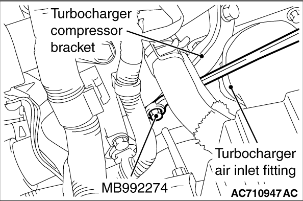
Use special MB992274 to remove the turbocharger compressor bracket mounting bolt (cylinder block side).
|
|
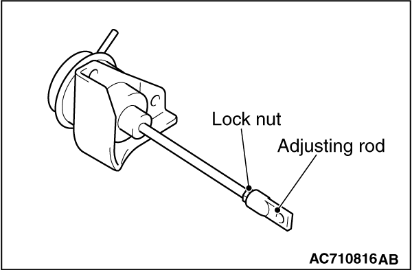
| caution |
Never loosen the locking nuts and adjusting rod of the waste gate actuator.
|
|
|
|
1.Clean the turbocharger oil feed tube, turbocharger water feed pipe and turbocharger water return pipe fitting, the inside of eye bolts, and individual pipe for clogs.
|
|
|
2.
| caution |
Take care not to allow foreign objects to get into the turbocharger.
|
Clean or use compressed air to remove any carbon particles stuck to the oil passage of the turbocharger.
|
|
|
3.Refill new engine oil at the turbocharger oil feed tube fitting hole of the turbocharger.
|
|
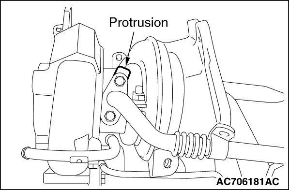
Install the gasket as its protrusion is in the direction shown. Install the gasket so that its protrusion faces in the direction shown in the illustration.
|
|
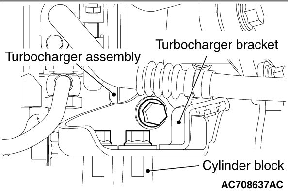
1.Check that the turbocharger bracket is in close contact with the turbocharger assembly and with the cylinder block, and then temporarily tighten the turbocharger bracket.
2.Tighten the bolt of the cylinder block side to the specified torque.
Tightening torque: 51 ± 7 N·m (38 ± 5 ft-lb)
3.Tighten the turbocharger bracket and the turbocharger assembly coupling bolt to the specified torque.
Tightening torque: 64 ± 5 N·m (48 ± 3 ft-lb)
|
|
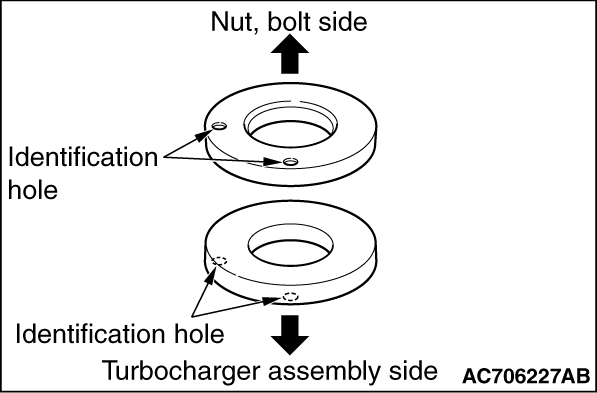
1.Tighten the bolts and nuts according to the procedure below.
(1)
Install two washers with their identification holes facing outside as shown in the figure.
(2)
Tighten the bolts and nuts to 29 ± 2 N·m (22 ± 1 ft-lb) in the order of number shown in the figure.
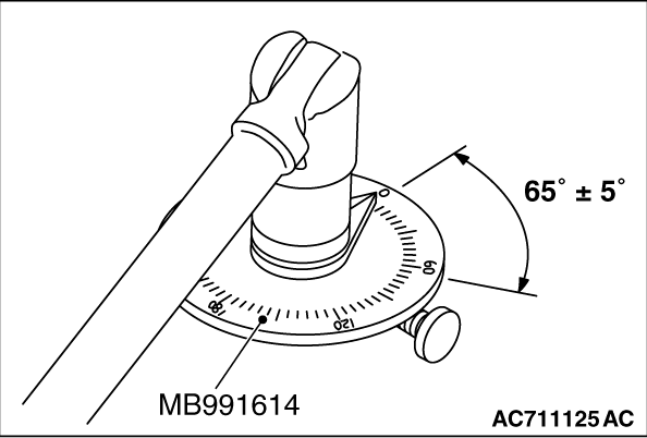
(3)
Use special tool MB991614 to tighten bolts and nuts 65 ± 5 degrees angle.
|
|
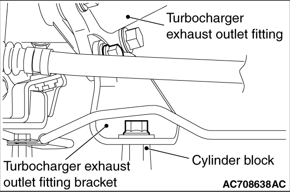
1.Check that the turbocharger exhaust outlet fitting bracket is in close contact with the turbocharger exhaust outlet fitting and with the cylinder block, and then temporarily tighten the turbocharger exhaust outlet fitting bracket.
2.Tighten the bolt of the cylinder block side to the specified torque.
Tightening torque: 51 ± 7 N·m (38 ± 5 ft-lb)
3.Tighten the bolt of the turbocharger exhaust outlet fitting bracket side to the specified torque.
Tightening torque: 64 ± 5 N·m (48 ± 3 ft-lb)
|
|
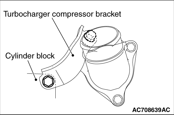
1.Check that the turbocharger compressor bracket is in close contact with the turbocharger assembly and with the cylinder block, and then temporarily tighten the turbocharger compressor bracket.
|
|
2.Use special tool MB992274 to tighten the turbocharger compressor bracket mounting bolt (cylinder block side) to the specified torque.
Tightening torque: 51 ± 7 N·m (38 ± 5 ft-lb)
3.Tighten the bolt of the turbocharger assembly side to the specified torque.
Tightening torque: 51 ± 7 N·m (38 ± 5 ft-lb)
|
![[Previous]](../../../buttons/fprev.png)
![[Next]](../../../buttons/fnext.png)
)
)
)
)
)
)
)
)
)
)