[Previous] [Next]

REMOVAL AND INSTALLATION


caution
  • Degrease the air hose and air pipe by isopropyl alcohol, parts cleaner (MZ100387) or equivalent.
  • As for the parts cleaner, use the petroleum cleaner whose major component is aliphatic hydrocarbon.
  • Working area should be airy and kept from flame.


Removal steps


1.
Turbocharger by-pass valve vacuum hose connection


2.
Turbocharger by-pass valve
<<A>>
>>A<<
3.
Charge air cooler intake hose A


4.
Charge air cooler intake pipe A
<<A>>
>>A<<
5.
Charge air cooler intake hose B


·
Air cleaner body (Refer to )
<<A>>
>>A<<
6.
Turbocharger by-pass valve hose
<<A>>
>>A<<
7.
Charge air cooler outlet hose E


·
Headlight support panel cover (Refer to GROUP 51, Front Bumper and Radiator Grille Assembly )


8.
Charge air cooler intake pipe B
<<A>>
>>A<<
9.
Charge air cooler intake hose D


·
Front bumper and radiator grille assembly (Refer to GROUP 51, Front Bumper and Radiator Grille Assembly )


10.
Charge air cooler outlet pipe C
<<A>>
>>A<<
11.
Charge air cooler outlet hose C


12.
Charge air cooler hanger bracket (LH)


13.
Charge air cooler hanger


14.
Charge air cooler assembly

REMOVAL SERVICE POINT


<<A>> AIR HOSE/AIR PIPE REMOVAL


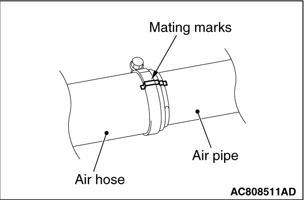
Put mating marks on the air hose, air pipe, and hose clamp, and remove them.

INSTALLATION SERVICE POINT


>>A<< AIR HOSE/AIR PIPE INSTALLATION


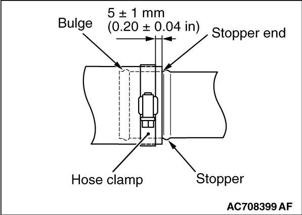
1.Insert hose to stopper end and not overlap with stopper.
2.Place the hose clamp as shown in the figure so that it does not overlap with the bulge and the stopper end. Then, set the hose clamp 5 ± 1 mm (0.20 ± 0.04 inch) away from the stopper.

3.
caution Do not use an electric screwdriver or air tool. Manually tighten the hose clamp.
Align the mating marks on the air hose, air pipe, and hose clamp. Then, tighten the hose clamp to the specified torque.
Tightening torque: 6.0 ± 1.0 N·m (54 ± 8 in-lb)