![[Previous]](../../../buttons/fprev.png)
![[Next]](../../../buttons/fnext.png)
DTC P0452: Evaporative
Emission Control System Pressure Sensor Low Input
CIRCUIT OPERATION
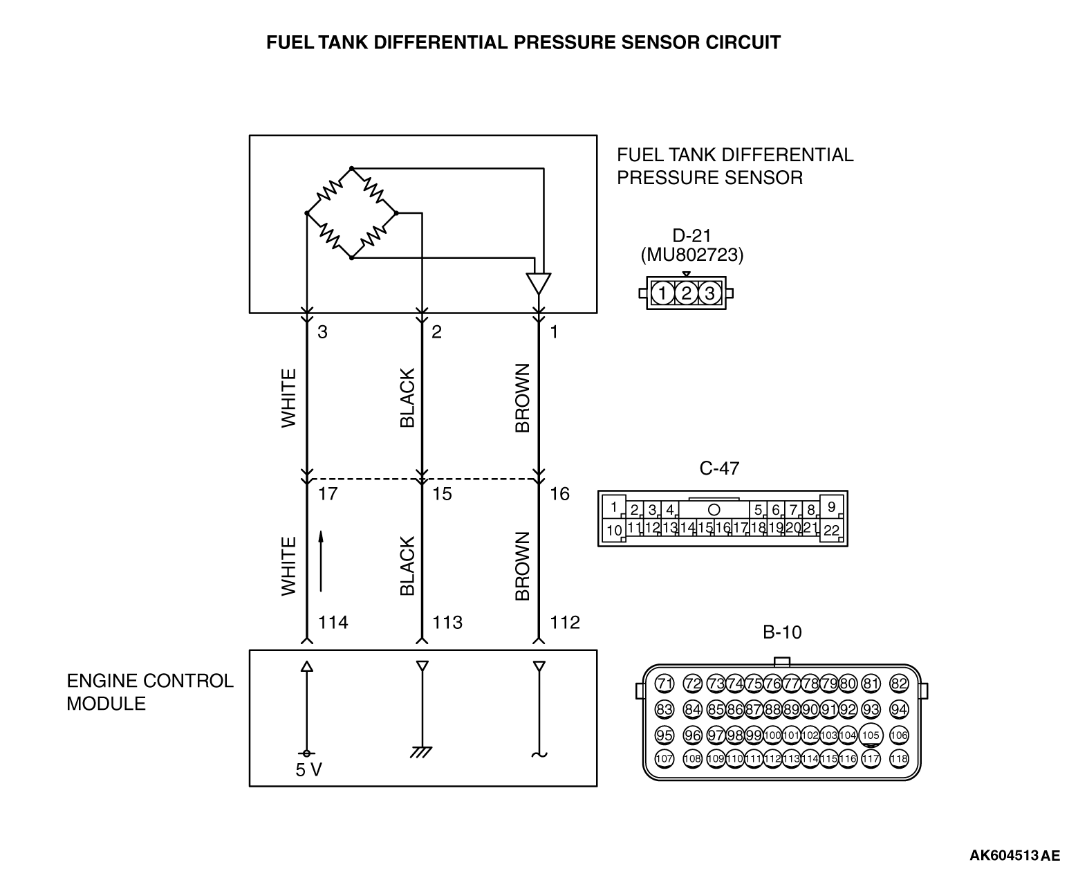
- The ECM (terminal No. 114) supplies a 5 volts reference
signal to the fuel tank differential pressure sensor (terminal No. 3). The fuel tank differential
pressure sensor (terminal No. 2) is grounded through the ECM (terminal No. 113).
- The fuel tank differential pressure sensor (terminal No. 1) returns a voltage signal
to the ECM (terminal No. 112) that is proportional to the pressure in the fuel tank.
TECHNICAL DESCRIPTION
- The ECM monitors the fuel tank differential pressure
sensor output voltage.
- The ECM determines whether the fuel tank differential pressure sensor signal voltage
is within normal operating parameters.
DESCRIPTIONS OF MONITOR METHODS
Fuel tank differential pressure sensor output voltage is out of specified range.
MONITOR EXECUTION
Continuous
MONITOR EXECUTION CONDITIONS (OTHER MONITOR AND SENSOR)
Other Monitor (There is no temporary DTC stored in memory for the item monitored
below)
- Evaporative emission purge solenoid monitor
- Evaporative emission ventilation solenoid monitor
- Fuel tank temperature sensor monitor
- Fuel level sensor monitor
Sensor (The sensors below are determined to be normal)
- Mass airflow sensor
- Barometric pressure sensor
- Intake air temperature sensor
- Engine coolant temperature sensor
- Accelerator pedal position sensor
DTC SET CONDITIONS
Logic Flow Chart (Monitor Sequence)
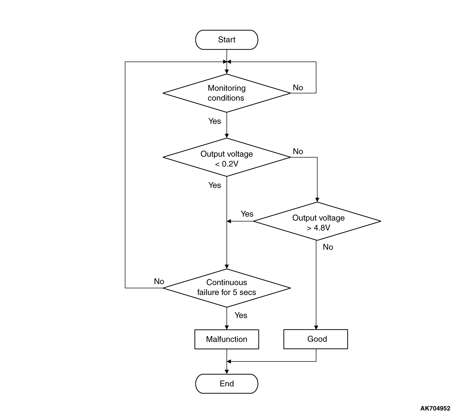
Check Condition
- 2 seconds or more have passed since the starting sequence was completed.
Judgement Criterion
- The fuel tank differential pressure sensor output voltage remains 0.2 volt or less
for 5 seconds.
FAIL-SAFE AND BACKUP FUNCTION
OBD-II DRIVE CYCLE PATTERN
Refer to Diagnostic Function - OBD-II Drive Cycle - Pattern 23  .
.
TROUBLESHOOTING HINTS (THE MOST LIKELY CAUSES FOR THIS CODE TO BE SET ARE:)
- Fuel tank differential pressure sensor failed.
- Open or shorted fuel tank differential pressure sensor circuit, connector damage.
- ECM failed.
|
|
Required Special Tools:
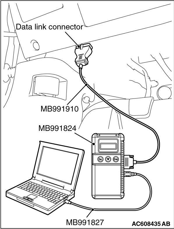
- MB991958: Scan Tool (M.U.T.-III Sub Assembly)
- MB991824: V.C.I.
- MB991827: M.U.T.-III USB Cable
- MB991910: M.U.T.-III Main Harness A
- MB992110: Power Plant ECU Check Harness
|
|
|
STEP 1. Using scan tool MB991958, check
data list item 52: Fuel Tank Differential Pressure Sensor.
|
|
| caution |
To prevent damage to scan tool MB991958, always turn the ignition switch to the "LOCK"
(OFF) position before connecting or disconnecting scan tool MB991958.
|
(1)Connect scan tool MB991958 to the data link connector.
|
|
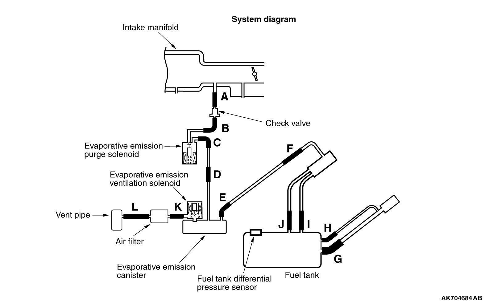
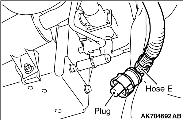
(2)Disconnect hose E from the evaporative emission canister, and plug the hose.
(3)Turn the ignition switch to the "ON" position.
(4)Remove the fuel cap.
(5)Set scan tool MB991958 to the data reading mode for item 52, Fuel Tank Differential
Pressure Sensor.
- Output voltage should be between 1,500 to 3,500 mV.
|
|
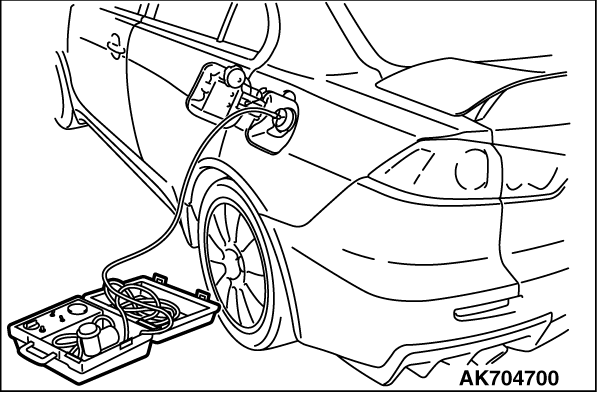
(6)Connect the evaporative emission system pressure pump (Miller number 6872A) to the fuel
tank filler tube by using fuel tank adapter (MLR-8382) and pressurize the fuel tank.
- The fuel tank pressure reading should increase.
(7)Turn the ignition switch to the "LOCK" (OFF) position. Then disconnect scan tool
MB991958.
(8)Remove the evaporative emission system pressure pump (Miller number 6872A) and
the fuel tank adapter (MLR-8382), and reinstall the fuel cap.
(9)Connect hose E to the evaporative emission canister.
Q.
Is the sensor operating properly?
 It can be assumed that this malfunction is intermittent. Refer
to GROUP 00, How to Use Troubleshooting/Inspection Service Points - How to
Cope with Intermittent Malfunctions . It can be assumed that this malfunction is intermittent. Refer
to GROUP 00, How to Use Troubleshooting/Inspection Service Points - How to
Cope with Intermittent Malfunctions .
 Go to Step 2 . Go to Step 2 .
|
|
|
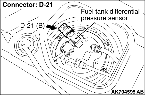
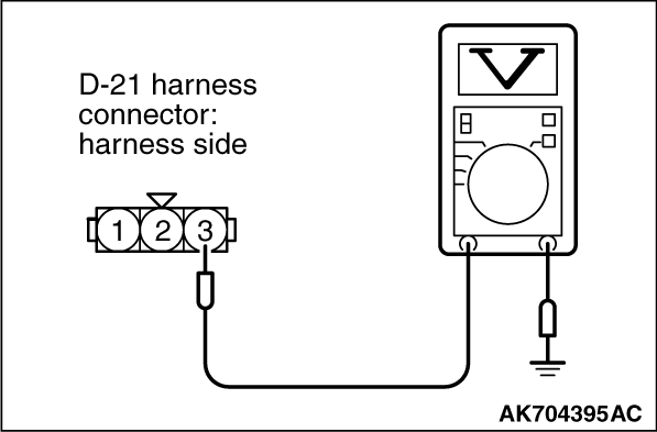
STEP 2. Measure the sensor supply voltage at fuel tank differential
pressure sensor connector D-21 by backprobing.
|
|
|
(1)Do not disconnect the connector D-21.
|
|
|
(2)Turn the ignition switch to the "ON" position.
|
|
(3)Measure the voltage between terminal No. 3 and ground by backprobing.
- Voltage should be between 4.9 and 5.1 volts.
(4)Turn the ignition switch to the "LOCK" (OFF) position.
Q.
Is the measured voltage between 4.9 and 5.1 volts?
Go to Step 8 .
Go to Step 3 .
|
|
|
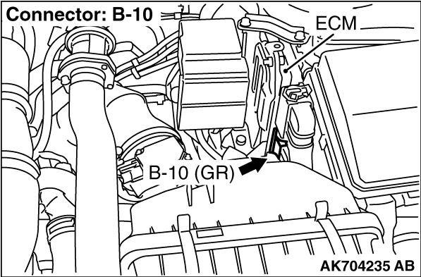
STEP 3. Check harness connector B-10 at ECM for damage.
|
|
|
Q.
Is the harness connector in good condition?
|
|
|
Go to Step 4 .
|
|
|
|
|
|
Repair or replace it. Refer to GROUP 00E, Harness Connector Inspection .
Then go to Step 12 .
|
|
|
|
|
|
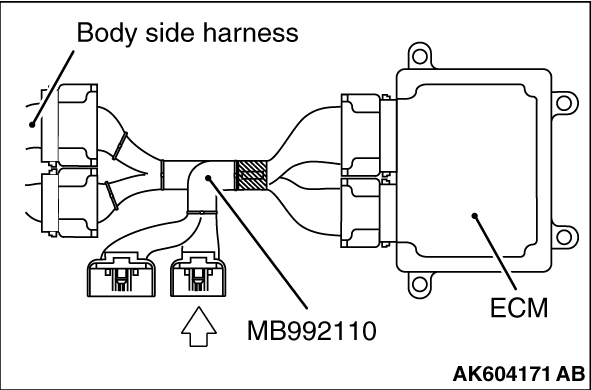
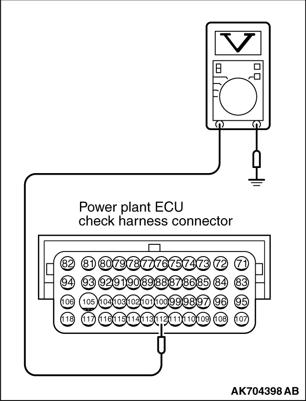
STEP 4. Measure the sensor supply voltage at ECM connector B-10 by
using power plant ECU check harness special tool MB992110.
|
|
(1)Disconnect all ECM connectors. Connect the power plant ECU check harness special
tool MB992110 between the separated connectors.
(2)Turn the ignition switch to the "ON" position.
|
|
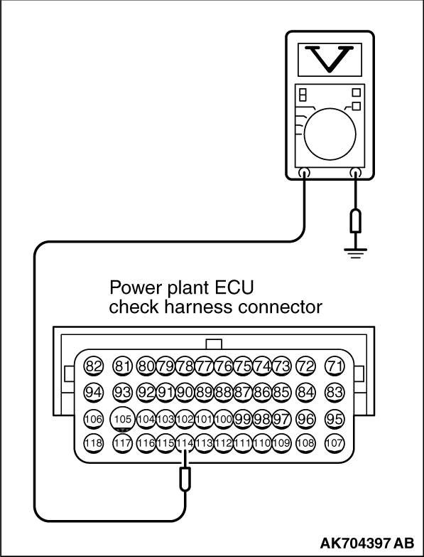
(3)Measure the voltage between terminal No. 114 and ground.
- Voltage should be between 4.9 and 5.1 volts.
(4)Turn the ignition switch to the "LOCK" (OFF) position.
Q.
Is the measured voltage between 4.9 and 5.1 volts?
Go to Step 7 .
Go to Step 5 .
|
|
|
STEP 5. Check harness connector D-21 at the fuel tank differential
pressure sensor for damage.
|
|
|
Q.
Is the harness connector in good condition?
|
|
|
Go to Step 6 .
|
|
|
|
|
|
Repair or replace it. Refer to GROUP 00E, Harness Connector Inspection .
Then go to Step 12 .
|
|
|
|
|
|
STEP 6. Check for short circuit to ground between fuel tank differential
pressure sensor connector D-21 (terminal No. 3) and ECM connector B-10 (terminal No. 114).
|
|
|
| note |
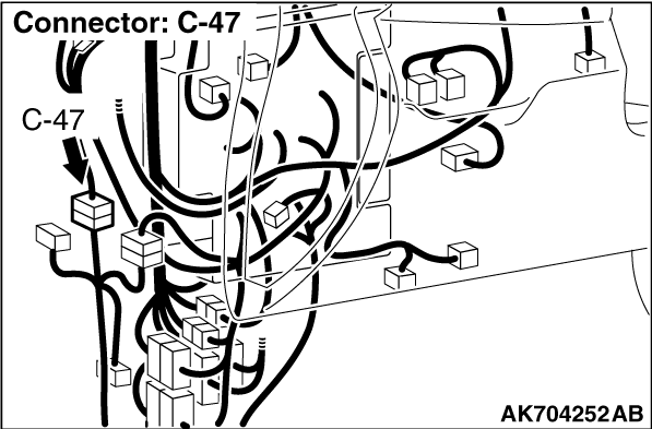
Check harness after checking intermediate connector C-47. If intermediate connector is
damaged, repair or replace it. Refer to GROUP 00E, Harness Connector Inspection . Then
go to Step 12.
|
|
|
|
Q.
Is the harness wire in good condition?
|
|
|
Go to Step 11 .
|
|
|
|
|
|
Repair it. Then go to Step 12 .
|
|
|
|
|
|
STEP 7. Check harness connector D-21 at the fuel tank differential
pressure sensor for damage.
|
|
|
Q.
Is the harness connector in good condition?
|
|
|
Check harness connector C-47 at intermediate connector for damage, and repair
or replace as required. Refer to GROUP 00E, Harness Connector Inspection .
If intermediate connector is in good condition, repair harness wire between fuel tank differential
pressure sensor connector D-21 (terminal No. 3) and ECM connector B-10 (terminal No. 114) because
of open circuit. Then go to Step 12 .
|
|
|
|
|
|
Repair or replace it. Refer to GROUP 00E, Harness Connector Inspection .
Then go to Step 12 .
|
|
|
|
|
|
STEP 8. Check harness connector D-21 at the fuel tank differential
pressure sensor and connector B-10 at ECM for damage.
|
|
|
Q.
Is the harness connector in good condition?
|
|
|
Go to Step 9 .
|
|
|
|
|
|
Repair or replace it. Refer to GROUP 00E, Harness Connector Inspection .
Then go to Step 12 .
|
|
|
|
|
|
STEP 9. Measure the sensor output voltage at ECM connector B-10 by
using power plant ECU check harness special tool MB992110.
|
|
(1)Disconnect all ECM connectors. Connect the power plant ECU check harness special
tool MB992110 between the separated connectors.
(2)Turn the ignition switch to the "ON" position.
(3)Remove the fuel cap
|
|
(4)Measure the voltage between terminal No. 112 and ground.
- Voltage should be between 1.5 and 3.5 volts.
(5)Turn the ignition switch to the "LOCK" (OFF) position.
Q.
Is the measured voltage normal?
Go to Step 11 .
Go to Step 10 .
|
|
|
STEP 10. Check for open circuit and short circuit to ground between
fuel tank differential pressure sensor connector D-21 (terminal No. 1) and ECM connector B-10 (terminal
No. 112).
|
|
|
| note |
Check harness after checking intermediate connector C-47. If intermediate connector is
damaged, repair or replace it. Refer to GROUP 00E, Harness Connector Inspection . Then
go to Step 12.
|
|
|
|
Q.
Is the harness wire in good condition?
|
|
|
Replace the fuel tank differential pressure sensor. Then go to Step 12 .
|
|
|
|
|
|
Repair it. Then go to Step 12 .
|
|
|
|
|
|
STEP 11. Using scan tool MB991958, check data list
item 52: Fuel Tank Differential Pressure Sensor.
|
|
| caution |
To prevent damage to scan tool MB991958, always turn the ignition switch to the "LOCK"
(OFF) position before connecting or disconnecting scan tool MB991958.
|
(1)Connect scan tool MB991958 to the data link connector.
|
|
(2)Disconnect hose E from the evaporative emission canister, and plug the hose.
(3)Turn the ignition switch to the "ON" position.
(4)Remove the fuel cap.
(5)Set scan tool MB991958 to the data reading mode for item 52, Fuel Tank Differential
Pressure Sensor.
- Output voltage should be between 1,500 to 3,500 mV.
|
|
(6)Connect the evaporative emission system pressure pump (Miller number 6872A) to the fuel
tank filler tube by using fuel tank adapter (MLR-8382) and pressurize the fuel tank.
- The fuel tank pressure reading should increase.
(7)Turn the ignition switch to the "LOCK" (OFF) position. Then disconnect scan tool
MB991958.
(8)Remove the evaporative emission system pressure pump (Miller number 6872A) and
the fuel tank adapter (MLR-8382), and reinstall the fuel cap.
(9)Connect hose E to the evaporative emission canister.
Q.
Is the sensor operating properly?
It can be assumed that this malfunction is intermittent. Refer to GROUP 00, How
to Use Troubleshooting/Intermittent Malfunctions .
Replace the ECM. When the ECM is replaced, register the ID code. Refer to GROUP
42B, Diagnosis - ID Code Registration Judgment Table <Vehicles with KOS> or
GROUP 42C, Diagnosis - ID Code Registration Judgment Table <Vehicles with WCM> .
Then go to Step 12 .
|
|
|
STEP 12. Test the OBD-II drive cycle.
|
|
|
(1)Carry out a test drive with the drive cycle pattern. Refer to Diagnostic Function - OBD-II
Drive Cycle - Pattern 23 .
|
|
|
(2)Check the diagnostic trouble code (DTC).
|
|
|
Retry the troubleshooting.
|
|
|
|
|
|
The inspection is complete.
|
|
|
|
)
)
)
)
)
)
)
)
)
)
)
)
)