![[Previous]](../../../buttons/fprev.png)
![[Next]](../../../buttons/fnext.png)
DTC P0327: Knock
Sensor Circuit Low
CIRCUIT OPERATION
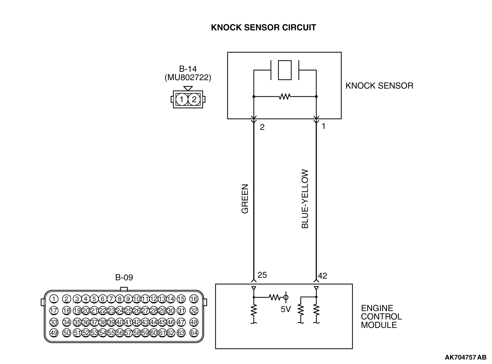
- The knock sensor (terminal No. 2) sends a signal voltage
to the ECM (terminal No. 25).
- The ground terminal (terminal No. 1) is grounded with ECM (terminal No. 42).
TECHNICAL DESCRIPTION
- The knock sensor converts the vibration of the cylinder
block into a voltage and outputs it.
- The ECM checks whether the voltage is within a specified range.
DESCRIPTIONS OF MONITOR METHODS
Knock sensor output voltage is out of specified range.
MONITOR EXECUTION
MONITOR EXECUTION CONDITIONS (Other monitor and Sensor)
Other Monitor (There is no temporary DTC stored in memory
for the item monitored below)
Sensor (The sensor below is determined to be normal)
DTC SET CONDITIONS
Logic Flow Chart
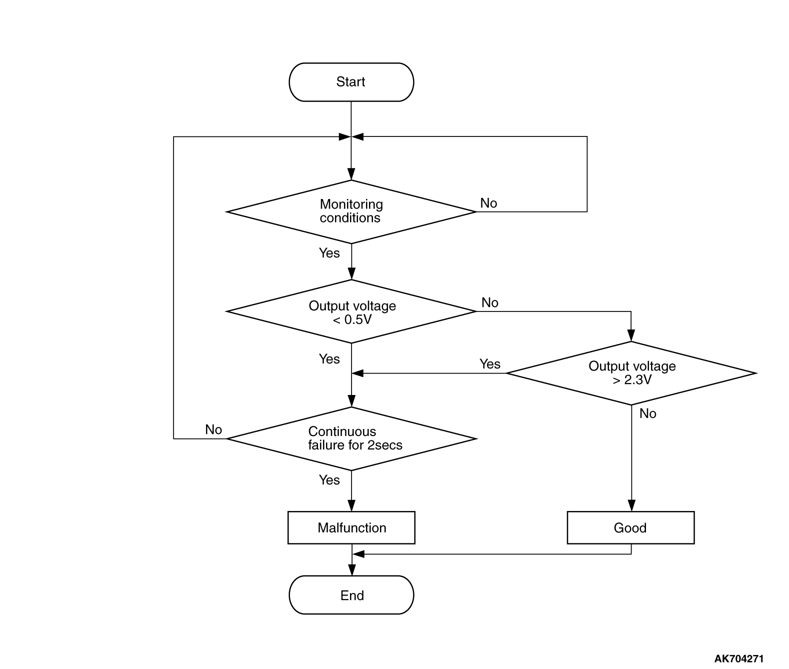
Check Condition
- 2 seconds or more have passed since the engine starting sequence was completed.
Judgement Criterion
- Knock sensor output voltage has continued to be lower than 0.5 volt for 2 seconds.
FAIL-SAFE AND BACKUP FUNCTION
- Fix the ignition timing with an allowance against knock.
OBD-II DRIVE CYCLE PATTERN
Refer to Diagnostic Function - OBD-II Drive Cycle - Pattern
23  .
.
TROUBLESHOOTING HINTS (The most likely causes for this code to be set are:)
- Knock sensor failed.
- Open or shorted knock sensor circuit or connector damage.
- ECM failed.
|
|
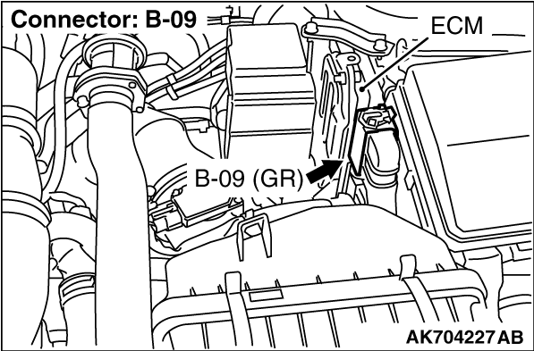
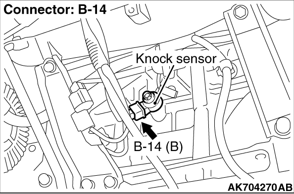
STEP 1. Check harness connector B-14 at the knock sensor
and harness connector B-09 at ECM for damage.
|
|
|
Q.
Is the harness connector in good condition?
|
|
|
 Go to Step 2. Go to Step 2.
|
|
|
|
|
|
 Repair or replace it. Refer to GROUP 00E, Harness Connector Inspection .
Then go to Step 5. Repair or replace it. Refer to GROUP 00E, Harness Connector Inspection .
Then go to Step 5.
|
|
|
|
|
|
STEP 2. Check for open circuit between knock sensor connector B-14
(terminal No. 1) and ECM connector B-09 (terminal No. 42).
|
|
|
Q.
Is the harness wire in good condition?
|
|
|
Go to Step 3.
|
|
|
|
|
|
Repair it. Then go to Step 5.
|
|
|
|
|
|
STEP 3. Check for open circuit and short circuit to ground between
knock sensor connector B-14 (terminal No. 2) and ECM connector B-09 (terminal No. 25).
|
|
|
Q.
Is the harness wire in good condition?
|
|
|
Go to Step 4.
|
|
|
|
|
|
Repair it. Then go to Step 5.
|
|
|
|
|
|
STEP 4. Replace the knock sensor.
|
|
|
(1)Replace the knock sensor.
|
|
|
(2)Turn the ignition switch to the "ON" position.
|
|
|
(3)After the DTC has been deleted, read the DTC again.
|
|
|
(4)Turn the ignition switch to the "LOCK" (OFF) position.
|
|
|
Replace the ECM. When the ECM is replaced, register the ID code. Refer to GROUP
42B, Diagnosis - ID Code Registration Judgment Table <Vehicles with KOS> or
GROUP 42C, Diagnosis - ID Codes Registration Judgment Table <Vehicles with WCM> .
Then go to Step 5.
|
|
|
|
|
|
Replace the knock sensor. Then go to Step 5.
|
|
|
|
|
|
STEP 5. Test the OBD-II drive cycle.
|
|
|
(1)Carry out a test drive with the drive cycle pattern. Refer to Diagnostic Function - OBD-II
Drive Cycle - Pattern 23 .
|
|
|
(2)Check the diagnostic trouble code (DTC).
|
|
|
Retry the troubleshooting.
|
|
|
|
|
|
The inspection is complete.
|
|
|
|
)
)
)
)