![[Previous]](../../../buttons/fprev.png)
![[Next]](../../../buttons/fnext.png)
DTC P0202: Injector
Circuit-Cylinder 2
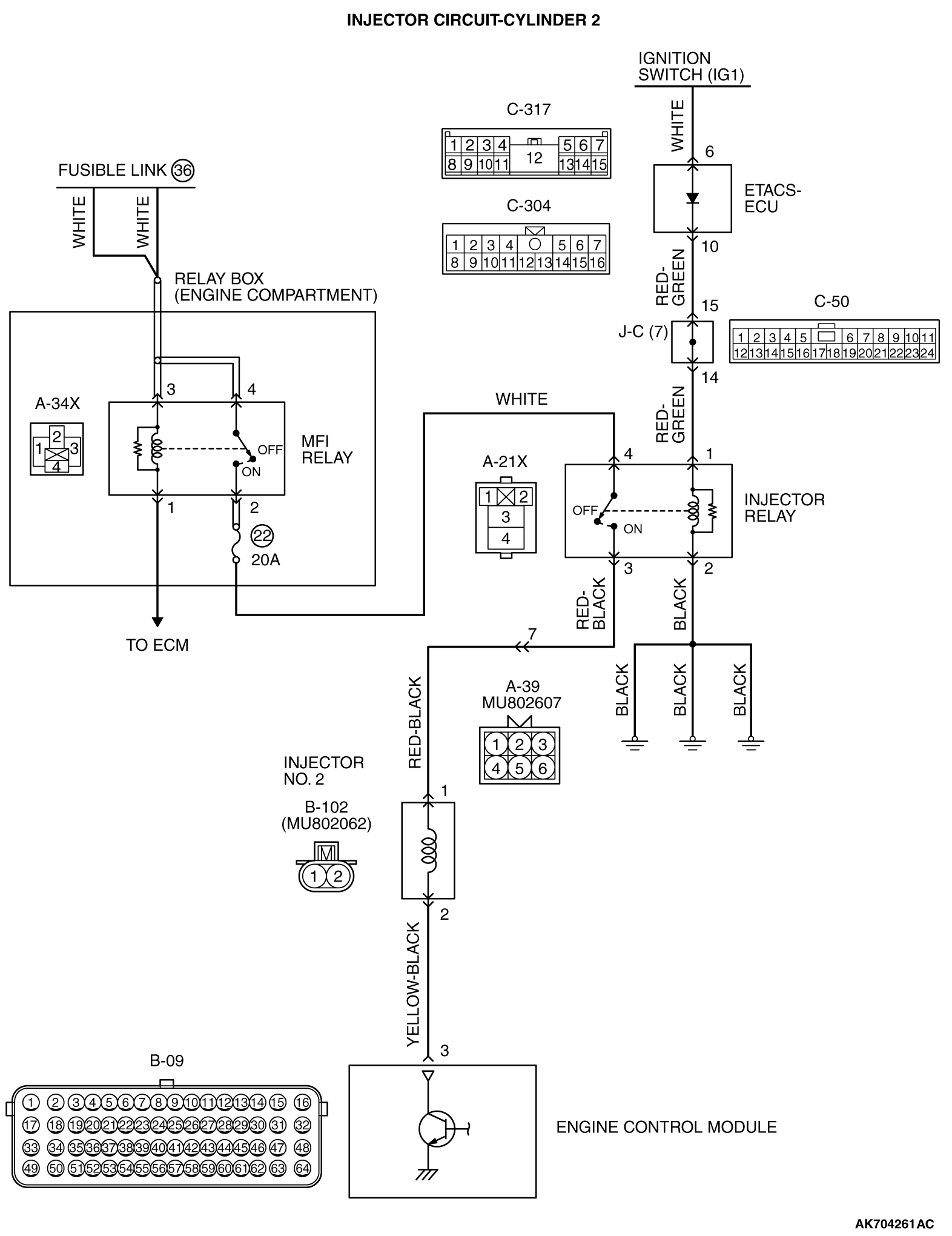
CIRCUIT OPERATION
- The injector power is supplied from the injector relay
(terminal No. 3).
- The ECM controls the injector by turning the power transistor in the ECM "ON" and "OFF".
TECHNICAL DESCRIPTION
- The amount of fuel injected by the injector is controlled
by the amount of continuity time the coil is grounded by the ECM.
DESCRIPTIONS OF MONITOR METHODS
The ECM detects open circuit and short malfunction.
MONITOR EXECUTION
MONITOR EXECUTION CONDITIONS (Other monitor and Sensor)
Other Monitor (There is no temporary DTC stored in memory
for the item monitored below)
Sensor (The sensor below is determined to be normal)
DTC SET CONDITIONS <Circuit continuity - open circuit
and shorted low>
Logic Flow Chart
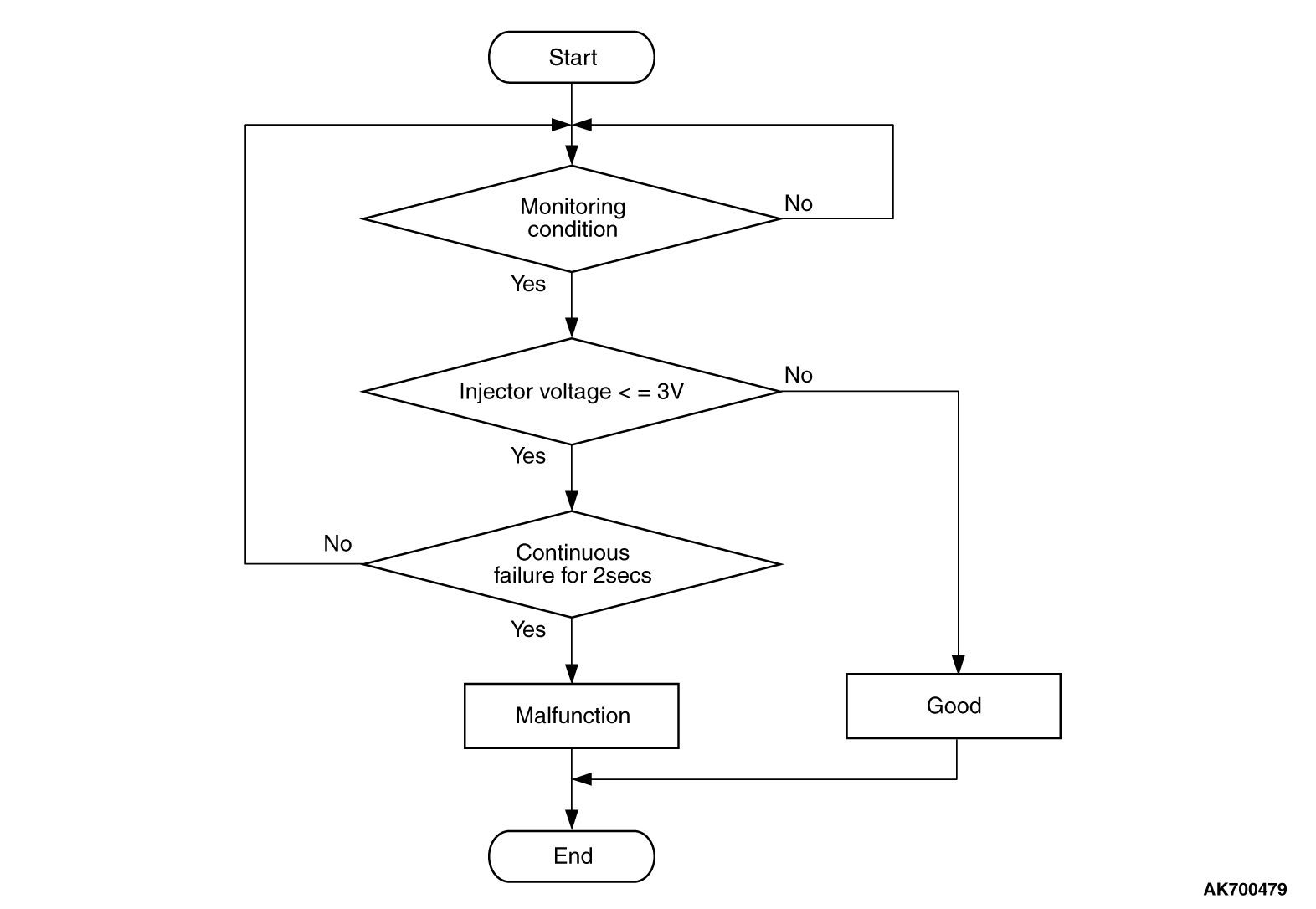
Check Condition
Judgement Criterion
- The supply voltage is 3 volts or less without the injector driving for 2 seconds.
DTC SET CONDITIONS <Circuit continuity - shorted
high>
Logic Flow Chart
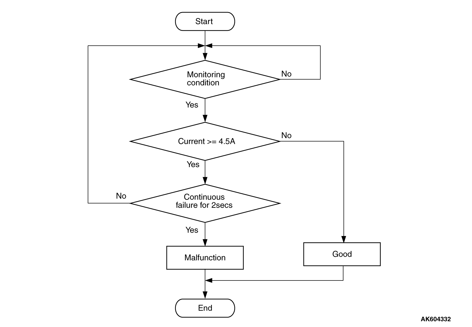
Check Condition
Judgement Criterion
- The coil current is 4.5 ampere or more with the injector driving for 2 seconds.
FAIL-SAFE AND BACKUP FUNCTION
OBD-II DRIVE CYCLE PATTERN
Refer to Diagnostic Function - OBD-II Drive
Cycle - Pattern 23  .
.
TROUBLESHOOTING HINTS (The most likely causes for this code to be set are:)
- No. 2 cylinder injector failed.
- Open or shorted No. 2 cylinder injector circuit, harness damage or connector damage.
- ECM failed.
|
|
Required Special Tools:
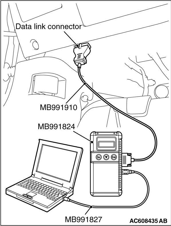
- MB991958: Scan Tool (M.U.T.-III Sub Assembly)
- MB991824: V.C.I.
- MB991827: USB Cable
- MB991910: Main Harness A
- MB991658: Test Harness
- MB992110: Power Plant ECU Check Harness
|
|
|
STEP 1. Using scan tool MB991958, check actuator test
item 1: Injectors.
|
|
| caution |
To prevent damage to scan tool MB991958, always turn the ignition switch to the "LOCK"
(OFF) position before connecting or disconnecting scan tool MB991958.
|
(1)Connect scan tool MB991958 to the data link connector.
(2)Start the engine and run at idle.
(3)Set scan tool MB991958 to the actuator testing mode for item 1, Injectors.
(4)Warm up the engine to normal operating temperature: 80°C to 95°C
(176°F to 203°F).
- The idle should become slightly rougher.
(5)Turn the ignition switch to the "LOCK" (OFF) position.
Q.
Is the actuator operating properly?
 It can be assumed that this malfunction is intermittent. Refer to GROUP 00, How
to Use Troubleshooting/Inspection Service Points - How to Cope with Intermittent
Malfunctions . It can be assumed that this malfunction is intermittent. Refer to GROUP 00, How
to Use Troubleshooting/Inspection Service Points - How to Cope with Intermittent
Malfunctions .
 Go to Step 2. Go to Step 2.
|
|
|
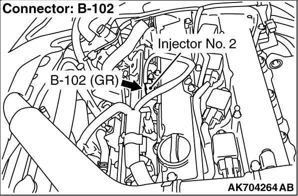
STEP 2. Check harness connector B-102 at No. 2 cylinder injector for
damage.
|
|
|
Q.
Is the harness connector in good condition?
|
|
|
Go to Step 3.
|
|
|
|
|
|
Repair or replace it. Refer to GROUP 00E, Harness Connector Inspection .
Then go to Step 20.
|
|
|
|
|
|
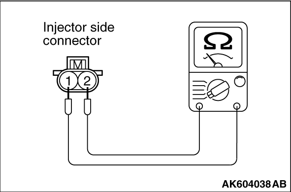
STEP 3. Check the No. 2 cylinder injector.
|
|
|
(1)Disconnect the No. 2 cylinder injector connector B-102.
|
|
(2)Measure the resistance between injector side connector terminal No. 1 and No. 2.
Standard value: 10.5 - 13.5 Ω [at 20°C (68°F)]
Q.
Is the measured resistance between 10.5 and 13.5 Ω [at 20°C
(68°F)]?
Go to Step 4.
Replace the No. 2 cylinder injector. Then go to Step 20.
|
|
|
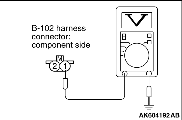
STEP 4. Measure the power supply voltage at No. 2 cylinder injector
connector.
|
|
|
(1)Disconnect connector B-102 and measure at the harness side.
|
|
|
(2)Turn the ignition switch to the "ON" position.
|
|
(3)Measure the voltage between terminal No. 1 and ground.
- Voltage should be battery positive voltage.
(4)Turn the ignition switch to the "LOCK" (OFF) position.
Q.
Is battery positive voltage (approximately 12 volts) present?
Go to Step 14.
Go to Step 5.
|
|
|
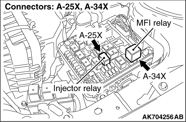
STEP 5. Check harness connector A-25X at injector relay for damage.
|
|
|
Q.
Is the harness connector in good condition?
|
|
|
Go to Step 6.
|
|
|
|
|
|
Repair or replace it. Refer to GROUP 00E, Harness Connector Inspection .
Then go to Step 20.
|
|
|
|
|
|
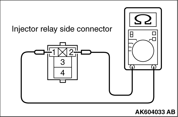
STEP 6. Check the injector relay.
|
|
|
(1)Remove the injector relay.
|
|
(2)Check for continuity between the injector relay terminal No. 1 and No. 2.
There should be continuity.
|
|
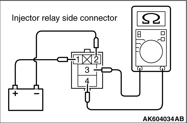
(3)Use jumper wires to connect injector relay terminal No. 1 to the positive battery terminal
and terminal No. 2 to the negative battery terminal.
(4)Check for continuity between the injector relay terminal No. 3 and No. 4 while
connecting and disconnecting the jumper wire at the negative battery terminal.
- Continuity (2 ohms or less). <Negative battery terminal connected>
- Should be open loop. <Negative battery terminal disconnected>
(5)Install the injector relay.
Q.
Is the measured resistance normal?
Go to Step 7.
Replace the injector relay. Then go to Step 20.
|
|
|
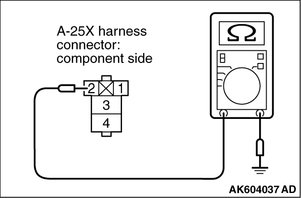
STEP 7. Check for continuity at injector relay harness side connector
A-25X.
|
|
|
(1)Disconnect the connector A-25X and measure at the harness side.
|
|
(2)Check for the continuity between terminal No. 2 and ground.
- Continuity (2 ohms or less).
Q.
Does continuity exist?
Go to Step 8.
Repair harness wire between injector relay connector A-25X (terminal No. 2) and
ground because of open circuit or harness damage. Then go to Step 20.
|
|
|
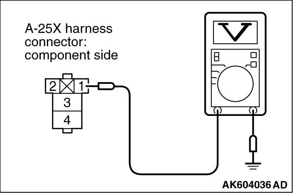
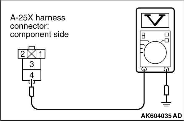
STEP 8. Measure the power supply voltage at injector relay harness
side connector A-25X.
|
|
|
(1)Disconnect the connector A-25X and measure at the harness side.
|
|
|
(2)Turn the ignition switch to the "ON" position.
|
|
(3)Measure the voltage between terminal No. 1 and ground.
- Voltage should be battery positive voltage.
Q.
Is battery positive voltage (approximately 12 volts) present?
Go to Step 10.
Go to Step 9.
|
|
|
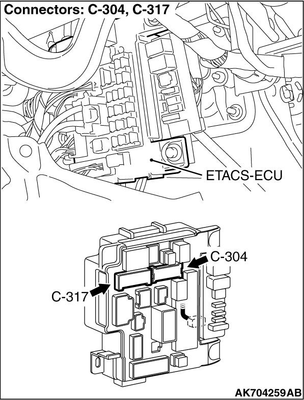
STEP 9. Check harness connector C-304 at ETACS-ECU for damage.
|
|
|
Q.
Is the harness connector in good condition?
|
|
|
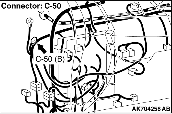
Check harness connector C-50 at intermediate connector for damage, and repair
or replace as required. Refer to GROUP 00E, Harness Connector Inspection .
If intermediate connector is in good condition, repair harness wire between injector relay connector
A-25X (terminal No. 1) and ETACS-ECU connector C-304 (terminal No. 10) because of open circuit
or short circuit to ground. Then go to Step 20.
|
|
|
|
|
|
Repair or replace it. Refer to GROUP 00E, Harness Connector Inspection .
Then go to Step 20.
|
|
|
|
|
|
STEP 10. Measure the power supply voltage at injector relay harness
side connector A-25X.
|
|
|
(1)Disconnect the connector A-25X and measure at the harness side.
|
|
|
(2)Turn the ignition switch to the "ON" position.
|
|
(3)Measure the voltage between terminal No. 4 and ground.
- Voltage should be battery positive voltage.
Q.
Is battery positive voltage (approximately 12 volts) present?
Go to Step 12.
Go to Step 11.
|
|
|
STEP 11. Check harness connector A-34X at MFI relay for damage.
|
|
|
Q.
Is the harness connector in good condition?
|
|
|
Repair harness wire between MFI relay connector
A-34X (terminal No. 2) and injector relay connector A-25X (terminal No. 4) because of open circuit
or short circuit to ground. Then go to Step 20.
|
|
|
|
|
|
Repair or replace it. Refer to GROUP 00E, Harness Connector Inspection .
Then go to Step 20.
|
|
|
|
|
|
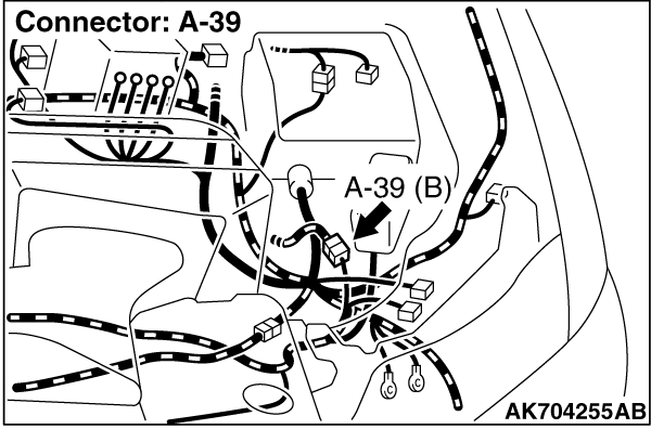
STEP 12. Check for open circuit or short circuit to ground between
injector relay connector A-25X (terminal No. 3) and No. 2 cylinder injector connector B-102
(terminal No. 1).
|
|
|
| note |
Check harness after checking intermediate connector A-39. If intermediate connector is damaged,
repair or replace it. Refer to GROUP 00E, Harness Connector Inspection .
Then go to Step 20 .
|
|
|
|
Q.
Is the harness wire in good condition?
|
|
|
Go to Step 13.
|
|
|
|
|
|
Repair it. Then go to Step 20.
|
|
|
|
|
|
STEP 13. Check harness connector C-304 at ETACS-ECU for damage.
|
|
|
Q.
Is the harness connector in good condition?
|
|
|
Check harness connector C-50 at intermediate connector for damage, and repair
or replace as required. Refer to GROUP 00E, Harness Connector Inspection .
If intermediate connector is in good condition, repair harness wire between injector relay connector
A-25X (terminal No. 1) and ETACS-ECU connector C-304 (terminal No. 10) because of harness damage.
Then go to Step 20.
|
|
|
|
|
|
Repair or replace it. Refer to GROUP 00E, Harness Connector Inspection .
Then go to Step 20.
|
|
|
|
|
|
STEP 14. Check harness connector A-34X at MFI relay for damage.
|
|
|
Q.
Is the harness connector in good condition?
|
|
|
Repair or replace it. Refer to GROUP 00E, Harness Connector Inspection .
Then go to Step 20.
|
|
|
|
|
|
STEP 15. Check for harness damage between MFI relay connector A-34X
(terminal No. 2) and injector relay connector A-25X (terminal No. 4).
|
|
|
Q.
Is the harness wire in good condition?
|
|
|
Go to Step 16.
|
|
|
|
|
|
Repair it. Then go to Step 20.
|
|
|
|
|
|
STEP 16. Check for harness damage between injector relay connector
A-25X (terminal No. 3) and No. 2 cylinder injector connector B-102 (terminal No. 1).
|
|
|
| note |
Check harness after checking intermediate connector A-39. If intermediate connector is damaged,
repair or replace it. Refer to GROUP 00E, Harness Connector Inspection .
Then go to Step 20 .
|
|
|
|
Q.
Is the harness wire in good condition?
|
|
|
Go to Step 17.
|
|
|
|
|
|
Repair it. Then go to Step 20.
|
|
|
|
|
|
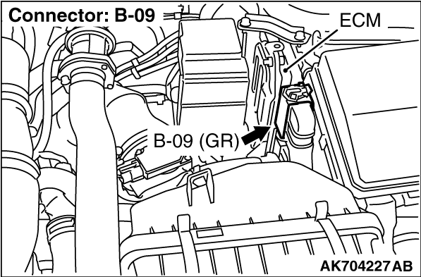
STEP 17. Check harness connector B-09 at ECM for damage.
|
|
|
Q.
Is the harness connector in good condition?
|
|
|
Go to Step 18.
|
|
|
|
|
|
Repair or replace it. Refer to GROUP 00E, Harness Connector Inspection .
Then go to Step 20.
|
|
|
|
|
|
STEP 18. Check for open circuit and short circuit to ground and harness
damage between No. 2 cylinder injector connector B-102 (terminal No. 2) and ECM connector B-09
(terminal No. 3).
|
|
|
Q.
Is the harness wire in good condition?
|
|
|
Go to Step 19.
|
|
|
|
|
|
Repair it. Then go to Step 20.
|
|
|
|
|
|
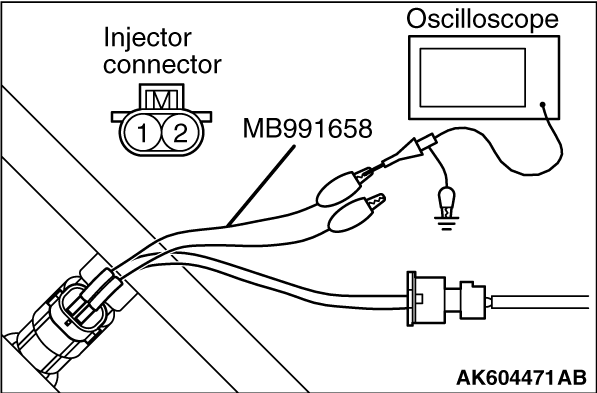
STEP 19. Using the oscilloscope, check the No. 2 cylinder injector.
|
|
|
(1)Disconnect the No. 2 cylinder injector connector B-102 and connect the test harness
special tool MB991658 between the separated connectors. (All terminals should be connected.)
|
|
(2)Connect the oscilloscope probe to the injector side connector terminal No. 2.
| note |
When measuring with the ECM side connector, disconnect all ECM connectors. Connect the
check harness special tool (MB992110) between the separated connectors. Then connect the oscilloscope
probe to the check harness connector terminal No. 3.
|
(3)Start the engine and run at idle.
|
|
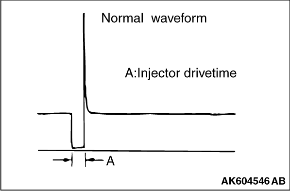
(4)Measure the waveform.
- The waveform should show a normal pattern similar to
the illustration.
(5)Turn the ignition switch to the "LOCK" (OFF) position.
Q.
Is the waveform normal?
It can be assumed that this malfunction is intermittent. Refer to GROUP 00, How
to Use Troubleshooting/Inspection Service Points - How to Cope with Intermittent
Malfunctions .
Replace the ECM. When the ECM is replaced, register the ID code. Refer to GROUP
42B, ID Code Registration Necessity Judgment Table <Vehicles with KOS> or
GROUP 42C, ID Codes Registration Judgment Table <Vehicles with WCM> .
Then go to Step 20.
|
|
|
STEP 20. Test the OBD-II drive cycle.
|
|
|
(1)Carry out a test drive with the drive cycle pattern. Refer to Diagnostic Function - OBD-II
Drive Cycle - Pattern 23 .
|
|
|
(2)Check the diagnostic trouble code (DTC).
|
|
|
Retry the troubleshooting.
|
|
|
|
|
|
The inspection is complete.
|
|
|
|
)
)
)
)
)
)
)
)
)
)
)
)
)
)
)
)
)
)
)