|
|
1.Remove all of the ignition coils.
|
|
|
2.Remove the cylinder head cover.
| caution |
Turn the crankshaft always clockwise.
|
|
|
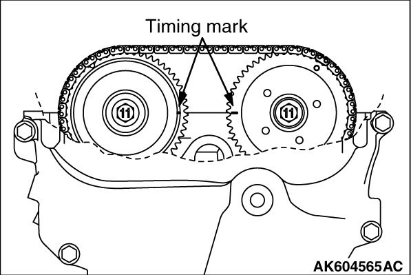
3.Turn the crankshaft clockwise, and align the timing mark on the exhaust camshaft sprocket against the upper face of the cylinder head as shown in Figure. Therefore, No.1 cylinder goes to the compression top dead center.
|
|
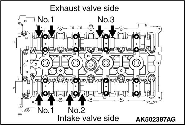
4.Using a thickness gauge, measure the valve clearance with the arrow shown in Figure. If deviated from the standard value, make note for the valve clearance.
Standard value:
Intake valve 0.20 ± 0.03 mm (0.008 ± 0.0012 inch)
Exhaust valve 0.30 ± 0.03 mm (0.012 ± 0.0012 inch)
|
|
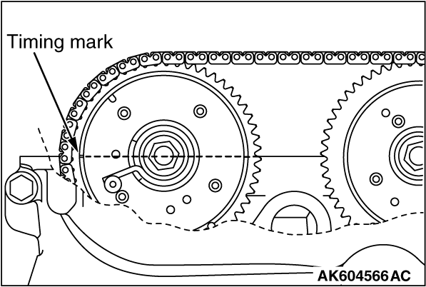
5.Turn the crankshaft clockwise 360 degrees, and put the timing mark on the exhaust camshaft sprocket in position shown in Figure. Therefore, No. 4 cylinder goes to the compression top dead center.
|
|
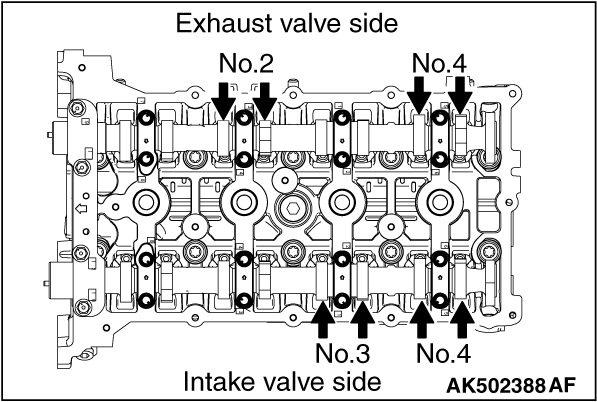
6.Check the valve clearance with the arrow shown in Figure. In the same procedure as 4.
7.If the valve clearance is deviated from the standard value, remove the camshaft and the valve tappet. For the camshaft removal, refer to Camshaft Removal and Installation  . .
|
|
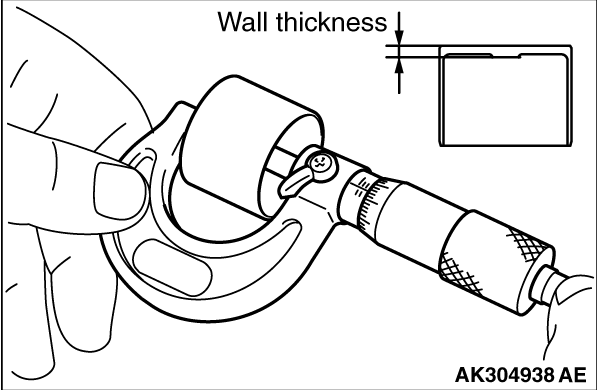
8.Using a micrometer, measure the thickness of the removed valve tappet.
|
|
9.Calculate the thickness of the newly installed valve tappet through the following equation.
A: thickness of newly installed valve tappet
B: thickness of removed valve tappet
C: measured valve clearance
Equation
Intake valve: A = B + [C - 0.20 mm (0.008 inch)]
Exhaust valve: A = B + [C - 0.30 mm (0.012 inch)]
| note |
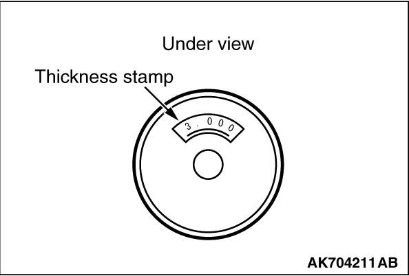
The valve tappet ranges 3,000 - 3,690 mm (0.1181 - 0.1453 inch) and has 47 types per 0.015 mm (0.0006 inch). The thickness below a decimal point is stamped on the reverse side of the valve tappet.
|
10.Install the valve tappet selected through the procedure 9, and put the camshaft in position. For the camshaft installation, refer to Camshaft Removal and Installation .
11.After installing the timing chain, measure the valve clearance using the procedure 3 to 6. Confirm the clearance is within the standard value.
| caution |
Completely remove all the old FIPG, which might be remaining among the components.
|
12.After completely removing the liquid gasket adhering on the timing chain case, cylinder block and cylinder head, degrease them with white gasoline.
| caution |
The cylinder head cover should be installed within 3 minutes of applying liquid gasket.
|
|

|
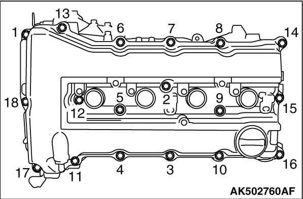
13.Apply a 4 mm bead of liquid gasket as illustrated.
Specified sealant:
THREE BOND 1217G or equivalent
|
|
14. Install the cylinder head cover and tighten the tightening bolts using the following procedures.
(1)
Temporarily tighten to the following torque in order shown in the illustration.
Tightening torque: 3.0 ± 1.0 N·m (27 ± 8 in-lb)
(2)
Tighten to the specified torque in order shown in the illustration.
Specified torque: 5.5 ± 0.5 N·m (49 ± 4 in-lb)
15.Install the ignition coils.
|
![[Previous]](../../../buttons/fprev.png)
![[Next]](../../../buttons/fnext.png)
)
)
)
)
)
)
)
)