![[Previous]](../../../buttons/fprev.png)
![[Next]](../../../buttons/fnext.png)
DTC U0151: SRS-ECU
Time-out
| caution |
If DTC U0151 is set in the A/C-ECU
or heater control unit <vehicles without A/C>, diagnose the CAN main bus line.
|
| caution |
Whenever the ECU is replaced, ensure that the communication
circuit is normal.
|
TROUBLE JUDGMENT
The A/C-ECU or heater control unit <vehicles without A/C> receives air conditioning
operation-related signals from the SRS-ECU via the CAN bus lines. If any of the air conditioning
control-related signals from the SRS-ECU cannot be received, the diagnostic trouble code U0151
is stored.
TECHNICAL DESCRIPTION (COMMENT)
Current trouble
- Connector(s) or wiring harness in the CAN bus lines between the SRS-ECU and the
A/C-ECU or heater control unit <vehicles without A/C>, the power supply system
to the SRS-ECU, the SRS-ECU itself, or the A/C-ECU or heater control unit <vehicles
without A/C> may be defective.
Past trouble
- If DTC U0151 is stored as a past trouble, carry out diagnosis with particular emphasis
on wiring and connector(s) in the CAN bus line between the A/C-ECU or heater control
unit <vehicles without A/C> and the SRS-ECU, and the power supply system to the SRS-ECU.
If the connectors and wiring are normal, and obviously the ECU is the cause of the trouble,
replace the ECU. If in doubt, do not replace the ECU.
| note |
For a past trouble, you cannot find it by the scan tool CAN bus diagnostics even if there
is a failure in CAN bus lines. In this case, refer to GROUP 00, How to Use Troubleshooting/Inspection
Service Points - How to Cope with Intermittent Malfunctions  )
and check the CAN bus lines. You can narrow down the possible cause of the trouble by referring
to the DTC, which is set regarding the CAN communication-linked ECUs (Refer to GROUP 54C, Explanation
about the scan too CAN bus diagnostics ). )
and check the CAN bus lines. You can narrow down the possible cause of the trouble by referring
to the DTC, which is set regarding the CAN communication-linked ECUs (Refer to GROUP 54C, Explanation
about the scan too CAN bus diagnostics ).
|
TROUBLESHOOTING HINTS
- Malfunction of the SRS-ECU
- Malfunction of the A/C-ECU or heater control unit <vehicles without
A/C>
- Damaged harness wires and connectors
|
|
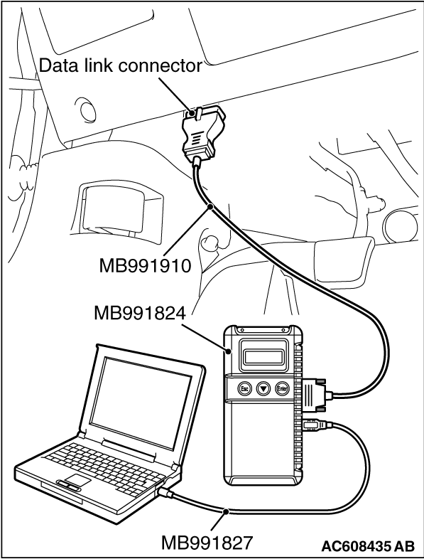
Required Special Tools:
- MB991223: Harness Set
- MB992006: Extra Fine Probe
- MB991958: Scan Tool (M.U.T.-III Sub Assembly)
- MB991824: V.C.I.
- MB991827: M.U.T.-III USB Cable
- MB991910: M.U.T.-III Main Harness A
|
|
|
STEP 1. Using scan tool MB991958, diagnose the CAN bus line
|
|
(1)
| caution |
To prevent damage to scan tool MB991958, always turn the ignition switch
to the "LOCK" (OFF) position before connecting or disconnecting scan tool MB991958.
|
Connect scan tool MB991958. Refer to "How to connect the Scan Tool (M.U.T.-III) ."
(2)Turn the ignition switch to the "ON" position.
(3)Diagnose the CAN bus line.
(4)Turn the ignition switch to the "LOCK" (OFF) position.
Q.
Is the CAN bus line found to be normal?
 Go to Step 2. Go to Step 2.
 Repair the CAN bus line. (Refer to GROUP 54C, Diagnosis ). Repair the CAN bus line. (Refer to GROUP 54C, Diagnosis ).
|
|
|
STEP 2. Using scan tool MB991958 read the SRS-ECU diagnostic trouble
code.
|
|
|
Check whether an SRS-ECU DTCs are set or not.
|
|
|
(1)Turn the ignition switch to the "ON" position.
|
|
|
(2)Check for SRS-ECU DTCs.
|
|
|
(3)Turn the ignition switch to the "LOCK" (OFF) position.
|
|
|
Diagnose the SRS-ECU (Refer to GROUP 52B, Diagnostic Trouble Code ).
|
|
|
|
|
|
Go to Step 3.
|
|
|
|
|
|
STEP 3. Using scan tool MB991958, check for any diagnostic trouble
code.
|
|
|
Check if a DTC, which relates to CAN communication-linked systems below, is set.
|
|
|
- ETACS-ECU
DTC indicating a time-out error related to the SRS-ECU system
|
|
|
(1)Turn the ignition switch to the "ON" position.
|
|
|
(2)Check for a DTC related to the relevant system.
|
|
|
(3)Turn the ignition switch to the "LOCK" (OFF) position.
|
|
|
Go to Step 4.
|
|
|
|
|
|
Go to Step 5.
|
|
|
|
|
|
STEP 4. Recheck for diagnostic trouble code.
|
|
|
Check again if the DTC is set.
|
|
|
(1)Turn the ignition switch to the "ON" position.
|
|
|
(2)Check if the DTC is set.
|
|
|
(3)Turn the ignition switch to the "LOCK" (OFF) position.
|
|
|
Replace the SRS-ECU. On completion, check that the DTC is not reset.
|
|
|
|
|
|
There is an intermittent malfunction such as poor engaged connector(s) or open
circuit (Refer to GROUP 00, How to Use Troubleshooting/Inspection Service Points - How
to Cope with Intermittent Malfunctions .)
|
|
|
|
|
|
STEP 5. Recheck for diagnostic trouble code.
|
|
|
Check again if the DTC is set.
|
|
|
(1)Turn the ignition switch to the "ON" position.
|
|
|
(2)Check if the DTC is set.
|
|
|
(3)Turn the ignition switch to the "LOCK" (OFF) position.
|
|
|
Replace the A/C-ECU or heater control unit <vehicles without A/C>.
On completion, check that the DTC is not reset.
|
|
|
|
|
|
There is an intermittent malfunction such as poor engaged connector(s) or open
circuit (Refer to GROUP 00, How to Use Troubleshooting/Inspection Service Points - How
to Cope with Intermittent Malfunctions .)
|
|
|
|
)