![[Previous]](../../../buttons/fprev.png)
![[Next]](../../../buttons/fnext.png)
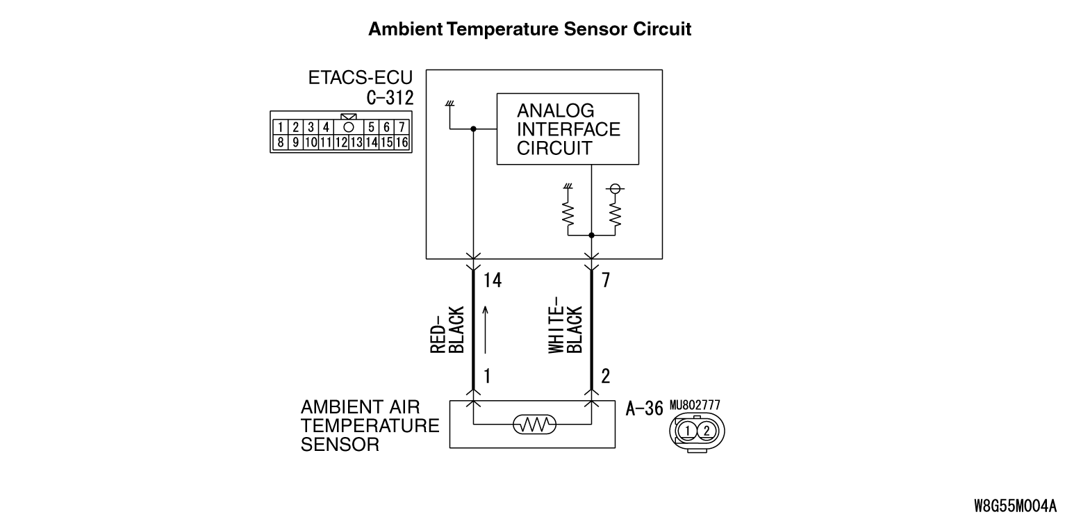
DTC B1034, B1035:
Ambient air temperature Sensor System
|
|
- DTC B1034 is set if there is a short circuit in the ambient air temperature
sensor input circuit.
- DTC B1035 is set if there is a defective connector connection, or if there is an
open circuit in the harness.
|
|
|
TECHNICAL DESCRIPTION (COMMENT)
|
|
|
Current trouble
- The A/C-ECU, the ambient air temperature sensor, or connector(s) or wiring
between the two may be defective.
|
|
|
Past trouble
- If DTC B1034 or B1035 is stored as a past trouble, carry out diagnosis with particular
emphasis on wiring and connector(s) between the A/C-ECU and the ambient air temperature
sensor. If the connectors and wiring are normal, and obviously the ECU is the cause of the trouble, replace
the ECU. If in doubt, do not replace the ECU.
|
|
|
- Malfunction of connector.
- Malfunction of the harness.
- Malfunction of the ambient air temperature sensor.
- Malfunction of the A/C-ECU.
|
|
|
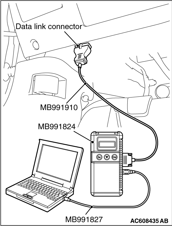
Required Special Tool:
- MB991958: Scan Tool (M.U.T.-III Sub Assembly)
- MB991824: Vehicle Communication Interface (V.C.I.)
- MB991827: M.U.T.-III USB Cable
- MB991910: M.U.T.-III Main Harness A
|
|
|
STEP 1. Using scan tool MB991958, diagnose the CAN bus line
|
|
(1)
| caution |
To prevent damage to scan tool MB991958, always turn the ignition switch
to the "LOCK" (OFF) position before connecting or disconnecting scan tool MB991958.
|
Connect scan tool MB991958. Refer to "How to connect the Scan Tool (M.U.T.-III)  ." ."
(2)Turn the ignition switch to the "ON" position.
(3)Diagnose the CAN bus line.
(4)Turn the ignition switch to the "LOCK" (OFF) position.
Q.
Is the CAN bus line found to be normal?
 Go to Step 2. Go to Step 2.
 Repair the CAN bus line. (Refer to GROUP 54C, Diagnosis ). Repair the CAN bus line. (Refer to GROUP 54C, Diagnosis ).
|
|
|
STEP 2. Recheck for diagnostic trouble code.
|
|
|
Recheck if the DTC is set.
|
|
|
(2)Turn the ignition switch to "ON" position.
|
|
|
(3)Check if the DTC is set.
|
|
|
Go to Step 3.
|
|
|
|
|
|
It can be assumed that this malfunction is intermittent. Refer to GROUP 00, How
to Use Troubleshooting/Inspection Service Points -
How to Cope with Intermittent
Malfunctions .
|
|
|
|
|
|
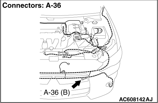
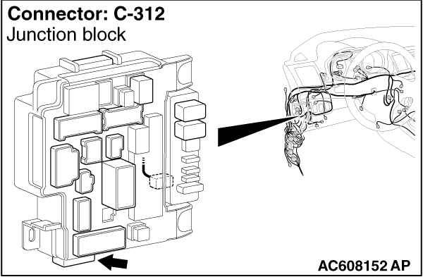
STEP 3. Check ambient air temperature sensor connector A-36 and ETACS-ECU
connector C-312 for loose, corroded or damaged terminals, or terminals pushed back in the connector.
|
|
|
Q.
Are ambient air temperature sensor connector A-36 and ETACS-ECU connector C-312 in
good condition?
|
|
|
Go to Step 4.
|
|
|
|
|
|
Repair or replace the connector. Refer to GROUP 00E, Harness Connector Inspection .
|
|
|
|
|
|
STEP 4. Check the wiring harness between ambient air temperature sensor
connector A-36 (terminals 2 and 1) and ETACS-ECU connector C-312 (terminals 7 and 14).
|
|
|
- Check the sensor signal line and earth line for open or short circuit.
|
|
|
Q.
Is the wiring harness between ambient air temperature sensor connector A-36 (terminals
2 and 1) and ETACS-ECU connector C-312 (terminals 7 and 14) in good condition?
|
|
|
Go to Step 5.
|
|
|
|
|
|
Repair the wiring harness.
|
|
|
|
|
|
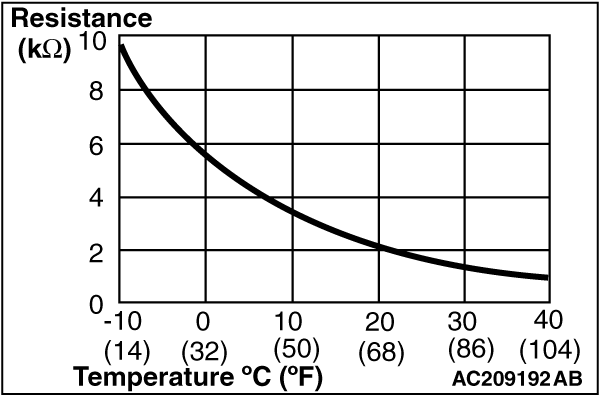
STEP 5. Check the ambient air temperature sensor.
|
|
Measure the resistance between connector terminals 1 and 2 under at least two different
temperatures. The resistance values should generally match those in the graph.
| note |
The temperature at the check should not exceed the range in the graph.
|
Q.
Is the ambient air temperature sensor in good condition?
Replace the A/C-ECU. Then go to Step 6.
Replace the ambient air temperature sensor. Then go to Step 6.
|
|
|
STEP 6. Recheck for diagnostic trouble code.
|
|
|
Check again if the DTC is set.
|
|
|
(1)Connect scan tool MB991958 to the data link connector
|
|
|
(2)Turn the ignition switch to the "ON" position.
|
|
|
(3)Check if the DTC is set.
|
|
|
(4)Turn the ignition switch to the "LOCK" (OFF) position.
|
|
|
Return to Step 1.
|
|
|
|
|
|
The procedure is complete.
|
|
|
|
)
)
)
)
)