![[Previous]](../../../buttons/fprev.png)
![[Next]](../../../buttons/fnext.png)
DIAGNOSTIC ITEM
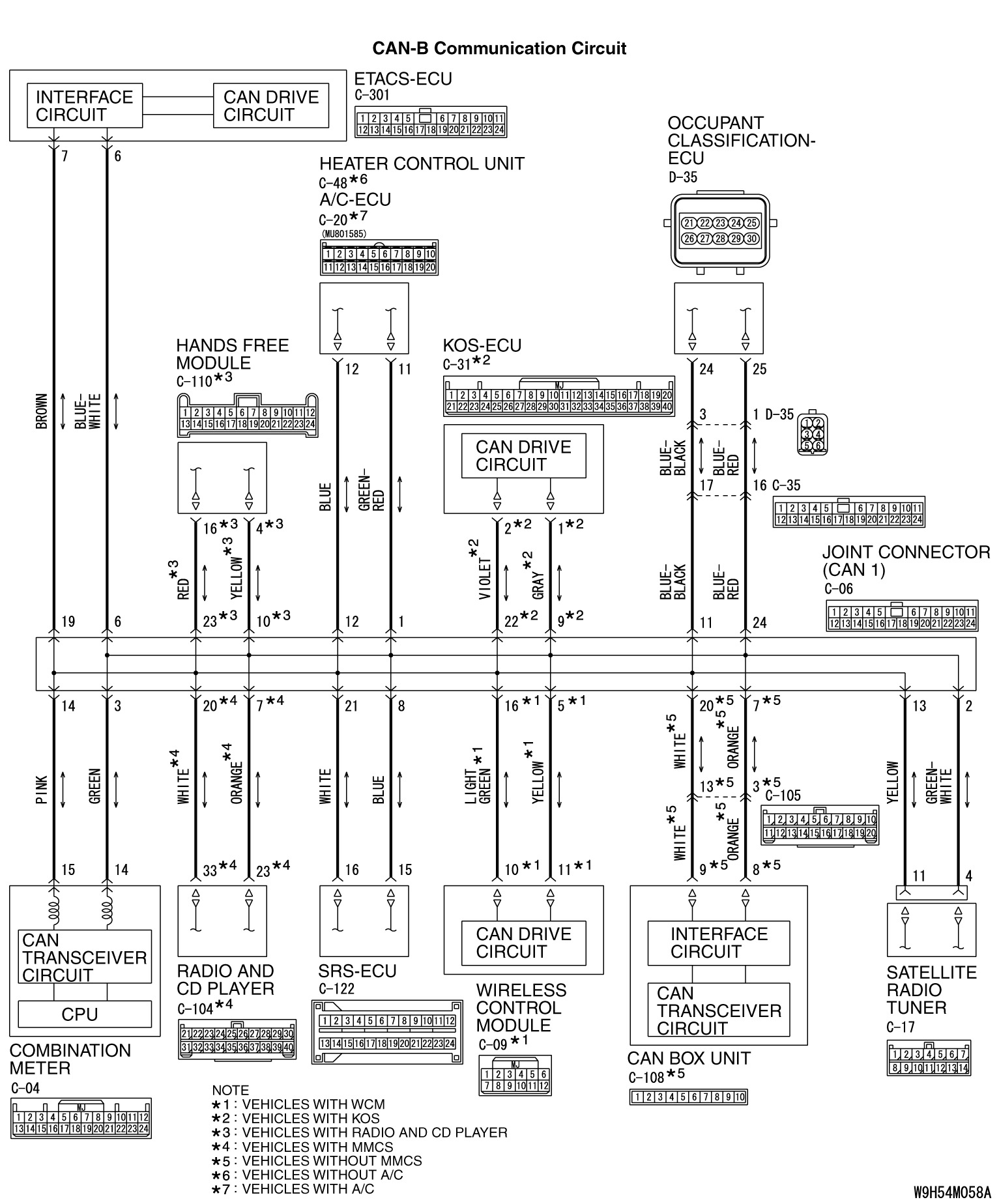
28: Short to power supply or ground, open circuit or line-to-line short in the CAN-B bus lines.
| caution |
When servicing a CAN bus line, ground yourself by
touching a metal object such as an unpainted water pipe. If you fail to do so, a component connected
to the CAN bus line may be damaged.
|
FUNCTION
If a short to power supply or ground, open circuit or line-to-line short is present at
either CAN_H or CAN_L side on the CAN-B lines, this diagnosis result will
be set.
TROUBLE JUDGEMENT CONDITIONS
When CAN-B lines communication is normal, and diagnostic trouble code U0019 is set, the
ETACS-ECU determines that there is a failure.
TROUBLESHOOTING HINTS
- Malfunction of the connector (short to power supply or ground in connector
or improperly connected)
- Malfunction of the wiring harness (short to power supply or ground, open circuit
or line-to-line short in CAN bus lines)
- Faulty ECU(s) (internal short to power supply or ground)
|
|
Required Special Tools:
- MB991223: Harness Set
- MB992006: Extra Fine Probe
|
|
|
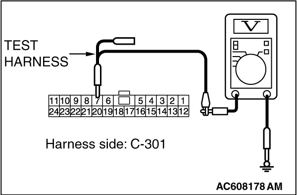
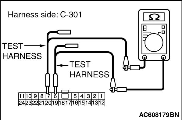
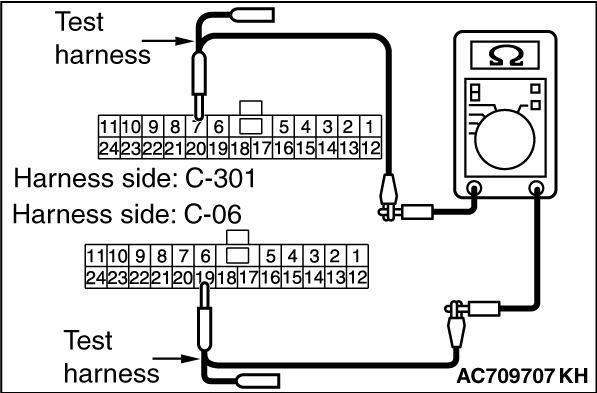
STEP 1. Check the wiring harness between ETACS-ECU connector
C-301 and body ground for a short to ground. Measure the resistance at ETACS-ECU connector C-301.
|
|
|
| caution |
Disconnect the negative battery terminal. For details refer to  . .
|
|
|
|
| caution |
A digital multimeter should be used. For details refer to .
|
|
|
|
| caution |
The test wiring harness should be used. For details refer to .
|
|
|
|
(1)Disconnect ETACS-ECU connector C-301, and measure the voltage at the wiring harness
side of ETACS-ECU connector.
|
|
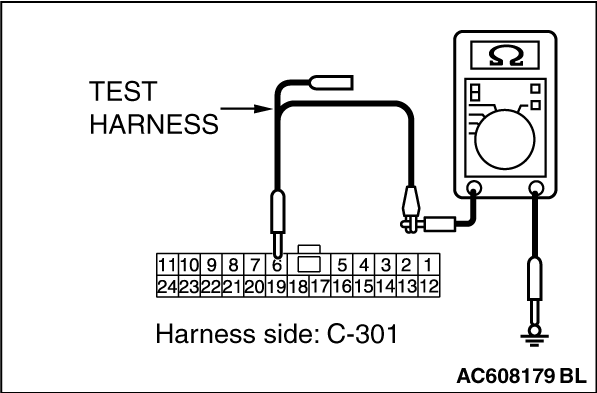
(2)Measure the resistance between ETACS-ECU connector terminal 6 and body ground.
OK: 1 kilo ohm or more
|
|
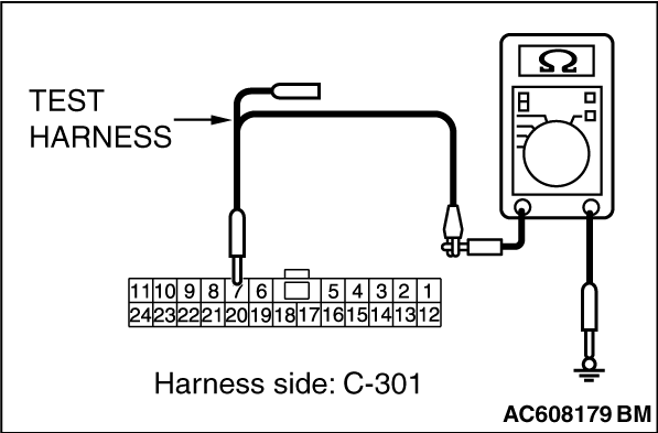
(3)Measure the resistance between ETACS-ECU connector terminal 7 and body ground.
OK: 1 kilo ohm or more
Q.
Do all the resistances measure 1 kilo ohm or more?
 Go to Step 2. Go to Step 2.
 Go to Step 13. Go to Step 13.
|
|
|
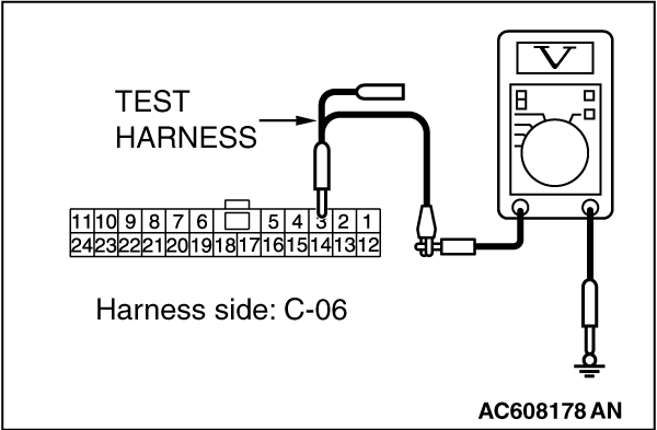
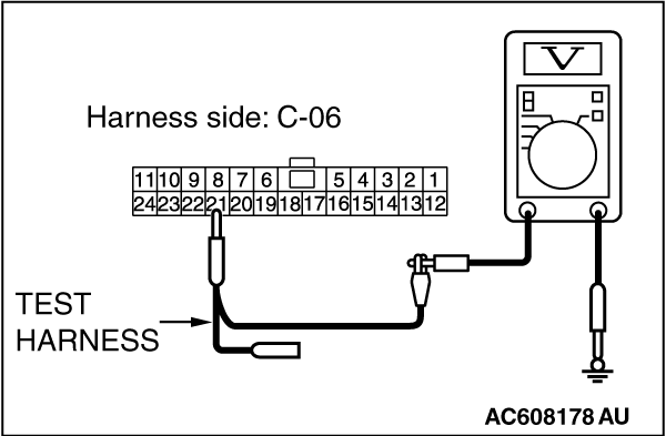
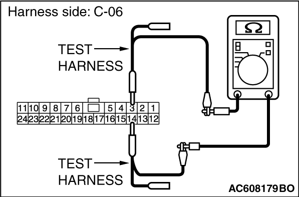
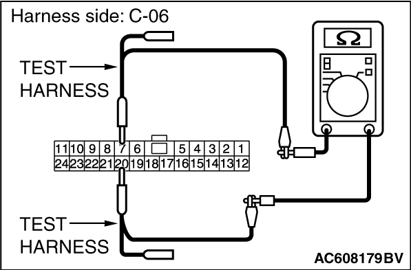
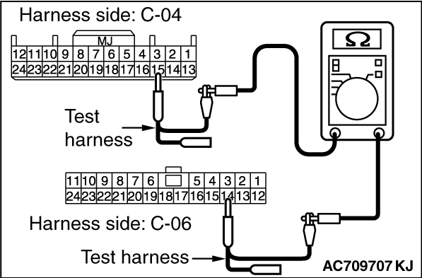
STEP 2. Check the wiring harness between joint connector (CAN1) C-06
and combination meter connector C-04 for a short to ground. Measure the resistance at joint
connector (CAN1) C-06.
|
|
|
(1)Disconnect joint connector (CAN1), and measure the resistance at the wiring harness
side of joint connector (CAN1).
|
|
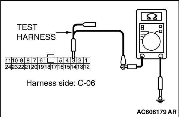
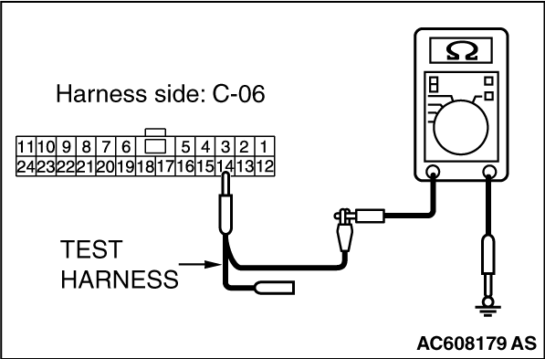
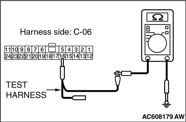
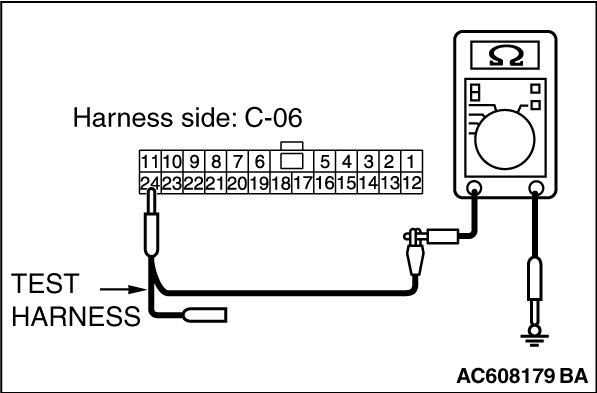
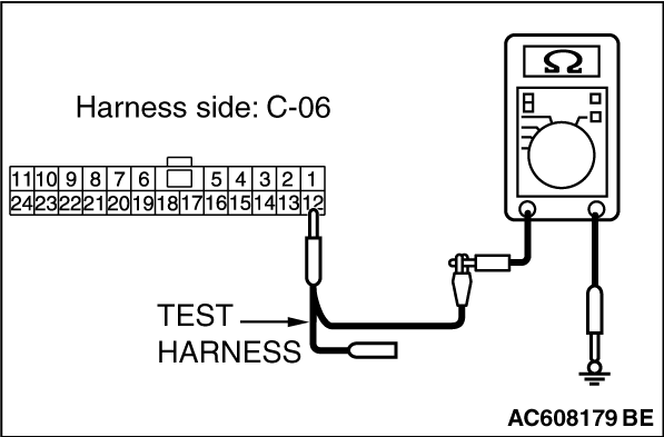
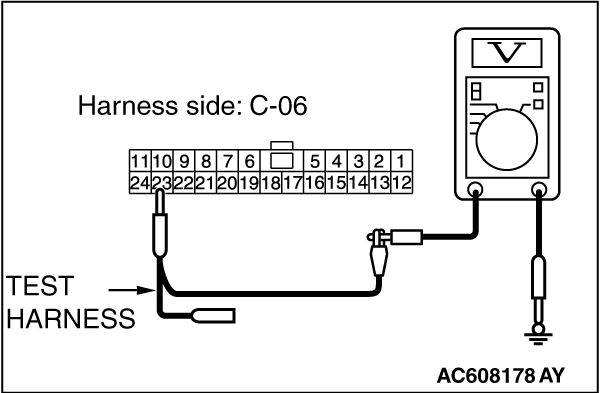
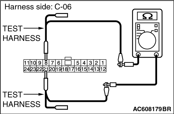
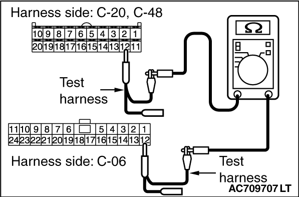
(2)Measure the resistance between joint connector (CAN1) terminal 3 and body ground.
OK: 1 kilo ohm or more
|
|
(3)Measure the resistance between joint connector (CAN1) terminal 14 and body ground.
OK: 1 kilo ohm or more
Q.
Do all the resistances measure 1 kilo ohm or more?
YES (vehicles with KOS) : Go to Step 3. : Go to Step 3.
YES (vehicles with WCM) : Go to Step 4.
NO (vehicles with KOS or WCM) : Go to Step 48.
|
|
|
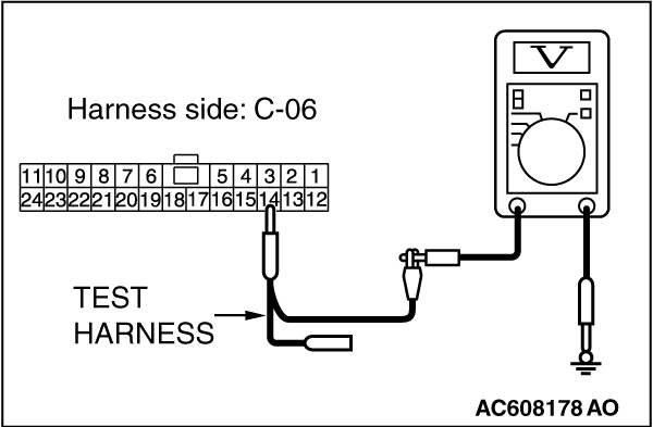
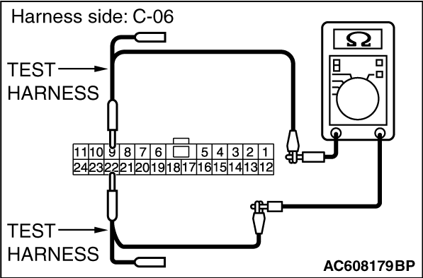
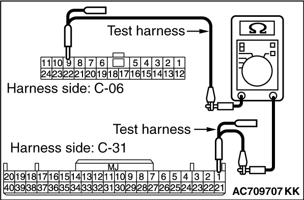
STEP 3. Check the wiring harness between joint connector (CAN1) C-06
and KOS-ECU connector C-31 for a short to ground. Measure the resistance at joint connector
(CAN1) C-06.
|
|
|
(1)Disconnect joint connector (CAN1), and measure the resistance at the wiring harness
side of joint connector (CAN1).
|
|
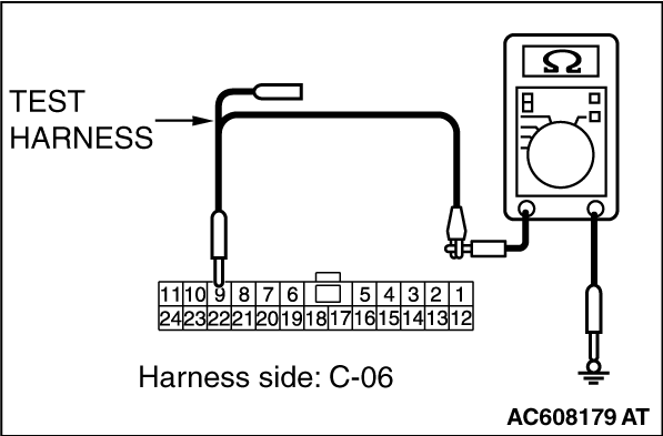
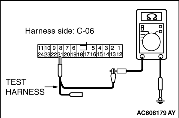
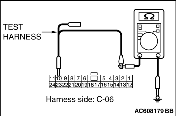
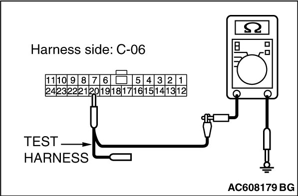
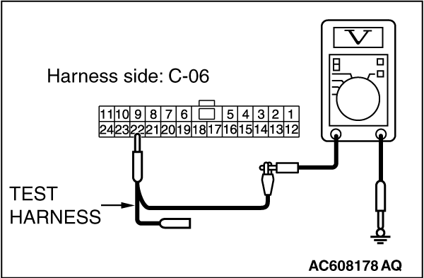
(2)Measure the resistance between joint connector (CAN1) terminal 9 and body ground.
OK: 1 kilo ohm or more
|
|
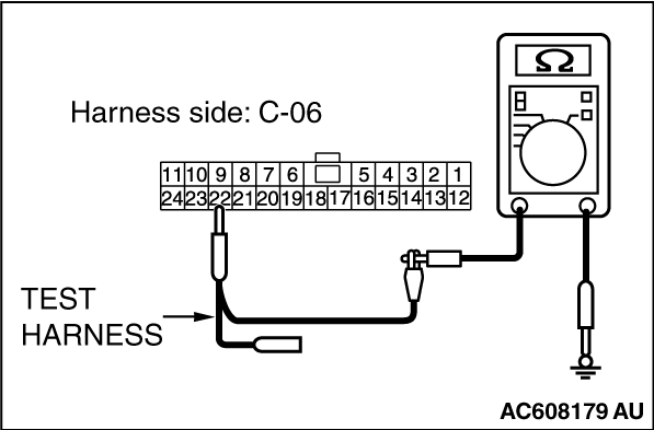
(3)Measure the resistance between joint connector (CAN1) terminal 22 and body ground.
OK: 1 kilo ohm or more
Q.
Do all the resistances measure 1 kilo ohm or more?
Go to Step 5.
Go to Step 49.
|
|
|
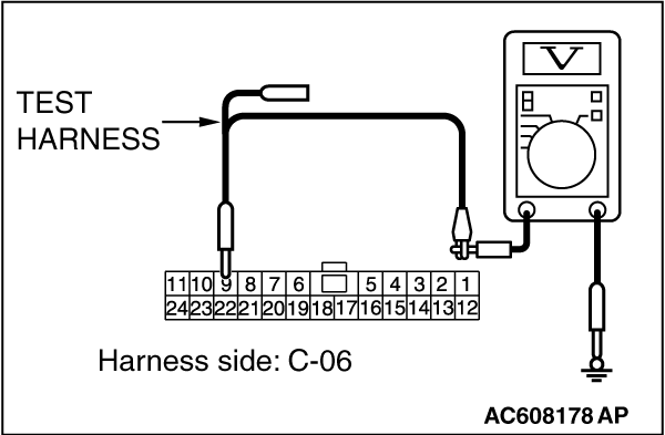
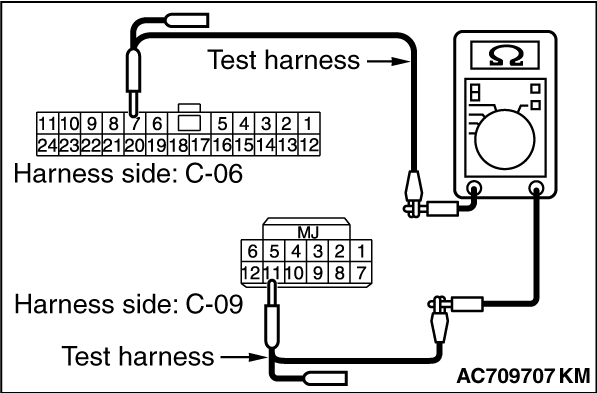
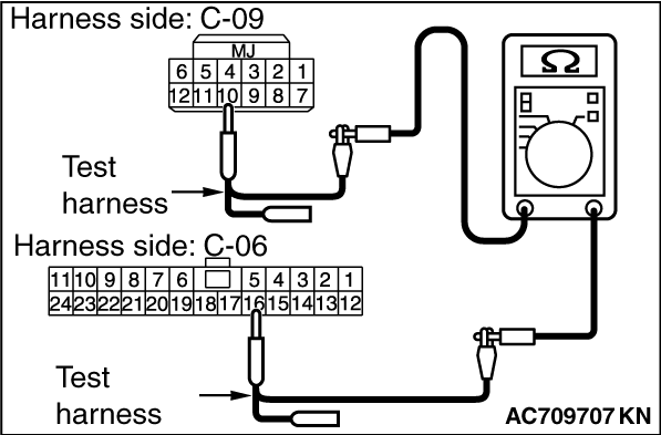
STEP 4. Check the wiring harness between joint connector (CAN1) C-06
and WCM connector C-09 for a short to ground. Measure the resistance at joint connector (CAN1) C-06.
|
|
|
(1)Disconnect joint connector (CAN1), and measure the resistance at the wiring harness
side of joint connector (CAN1).
|
|
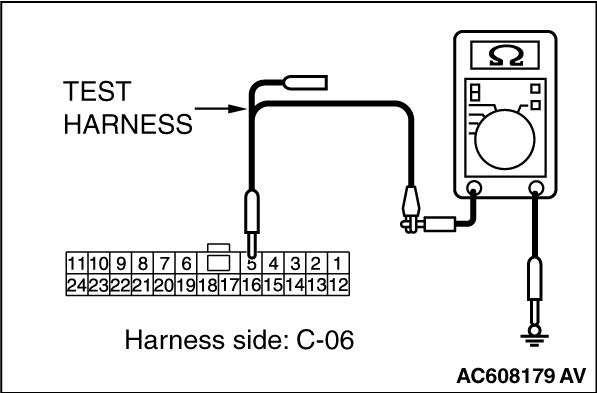
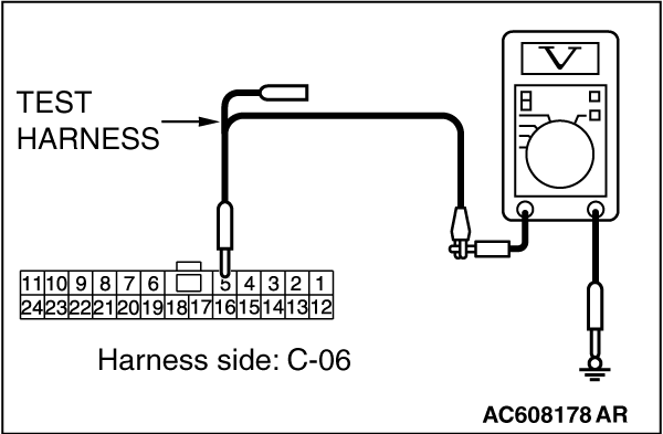
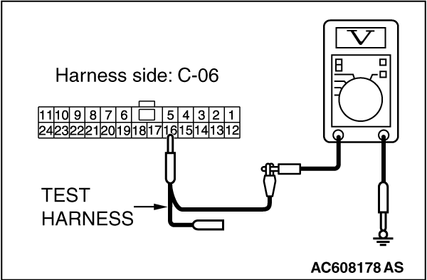
(2)Measure the resistance between joint connector (CAN1) terminal 5 and body ground.
OK: 1 kilo ohm or more
|
|
(3)Measure the resistance between joint connector (CAN1) terminal 16 and body ground.
OK: 1 kilo ohm or more
Q.
Do all the resistances measure 1 kilo ohm or more?
Go to Step 5.
Go to Step 50.
|
|
|
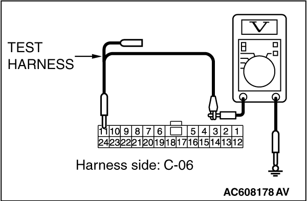
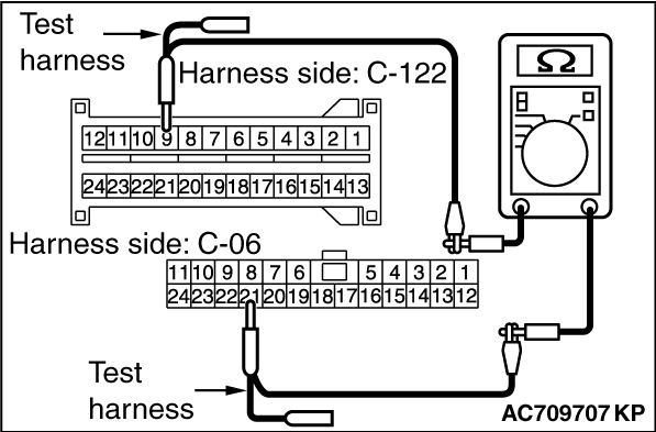
STEP 5. Check the wiring harness between joint connector (CAN1) C-06
and SRS-ECU connector C-122 for a short to ground. Measure the resistance at joint connector
(CAN1) C-06.
|
|
|
(1)Disconnect joint connector (CAN1), and measure the resistance at the wiring harness
side of joint connector (CAN1).
|
|
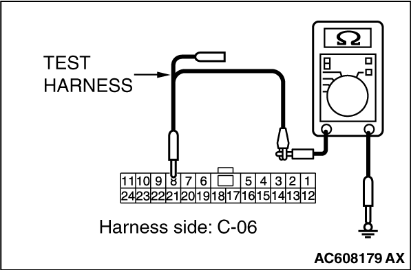
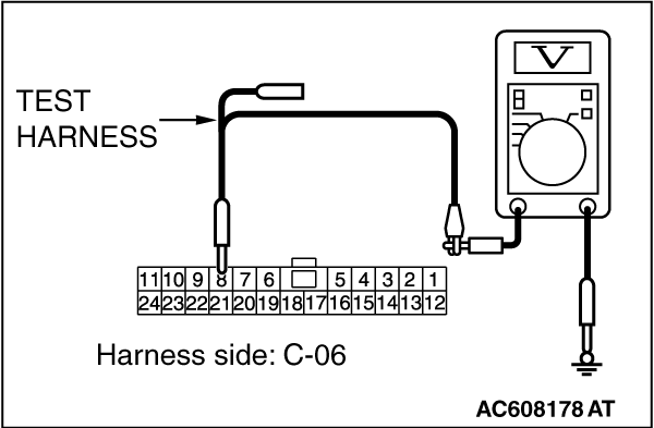
(2)Measure the resistance between joint connector (CAN1) terminal 8 and body ground.
OK: 1 kilo ohm or more
|
|
(3)Measure the resistance between joint connector (CAN1) terminal 21 and body ground.
OK: 1 kilo ohm or more
Q.
Do all the resistances measure 1 kilo ohm or more?
Go to Step 6.
Go to Step 51.
|
|
|
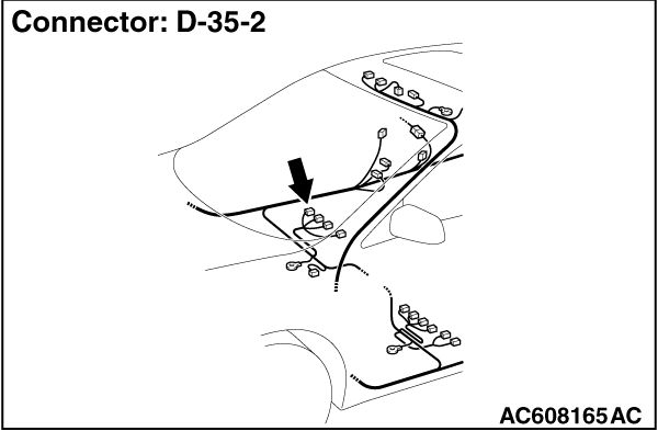
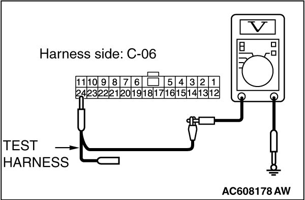
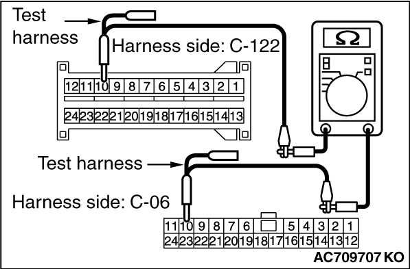
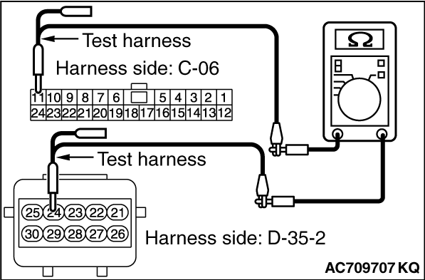
STEP 6. Check the wiring harness between joint connector (CAN1) C-06
and occupant classification-ECU connector D-35-2 for a short to ground. Measure the resistance
at joint connector (CAN1) C-06.
|
|
|
(1)Disconnect joint connector (CAN1), and measure the resistance at the wiring harness
side of joint connector (CAN1).
|
|
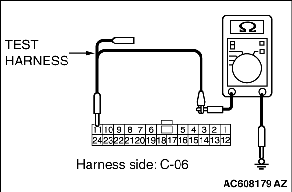
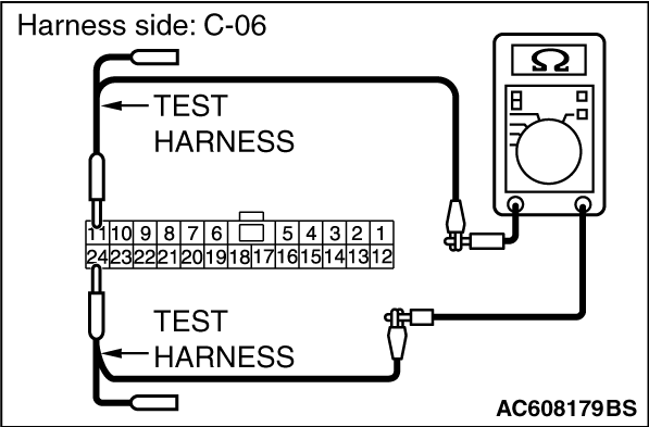
(2)Measure the resistance between joint connector (CAN1) terminal 11 and body ground.
OK: 1 kilo ohm or more
|
|
(3)Measure the resistance between joint connector (CAN1) terminal 24 and body ground.
OK: 1 kilo ohm or more
Q.
Do all the resistances measure 1 kilo ohm or more?
YES (vehicles without hands free system) : Go to Step 8.
YES (vehicles with hands free system) : Go to Step 7.
NO : Go to Step 52.
|
|
|
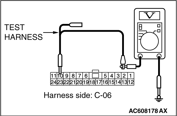
STEP 7. Check the wiring harness between joint connector (CAN1) C-06
and hands free module connector C-110 for a short to ground. Measure the resistance at joint
connector (CAN1) C-06.
|
|
|
(1)Disconnect joint connector (CAN1), and measure the resistance at the wiring harness
side of joint connector (CAN1).
|
|
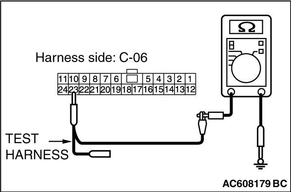
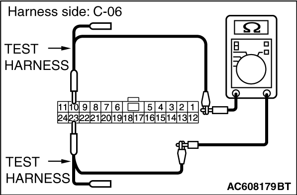
(2)Measure the resistance between joint connector (CAN1) terminal 10 and body ground.
OK: 1 kilo ohm or more
|
|
(3)Measure the resistance between joint connector (CAN1) terminal 23 and body ground.
OK: 1 kilo ohm or more
Q.
Do all the resistances measure 1 kilo ohm or more?
Go to Step 8.
Go to Step 53.
|
|
|
STEP 8. Check the wiring harness between joint connector (CAN1) C-06
and A/C-ECU connector C-20 <vehicles with A/C> or heater control unit connector
C-48 <vehicles without A/C> for a short to ground. Measure the resistance at joint connector
(CAN1) C-06.
|
|
|
(1)Disconnect joint connector (CAN1), and measure the resistance at the wiring harness
side of joint connector (CAN1).
|
|
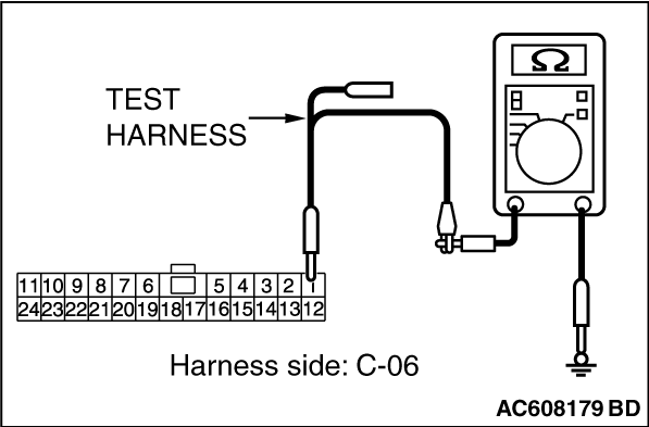
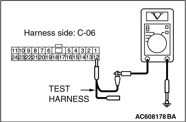
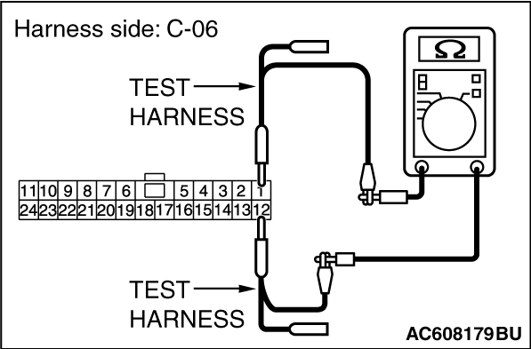
(2)Measure the resistance between joint connector (CAN1) terminal 1 and body ground.
OK: 1 kilo ohm or more
|
|
(3)Measure the resistance between joint connector (CAN1) terminal 12 and body ground.
OK: 1 kilo ohm or more
Q.
Do all the resistances measure 1 kilo ohm or more?
YES (vehicles without MMCS) : Go to Step 9.
YES (vehicles with MMCS) : Go to Step 10.
NO : Go to Step 54.
|
|
|
STEP 9. Check the wiring harness between joint connector (CAN1) C-06
and radio and CD player or CD changer connector C-104 for a short to ground. Measure the resistance
at joint connector (CAN1) C-06.
|
|
|
(1)Disconnect joint connector (CAN1), and measure the resistance at the wiring harness
side of joint connector (CAN1).
|
|
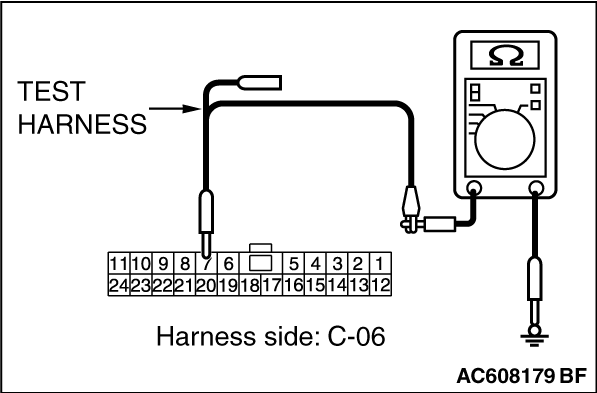
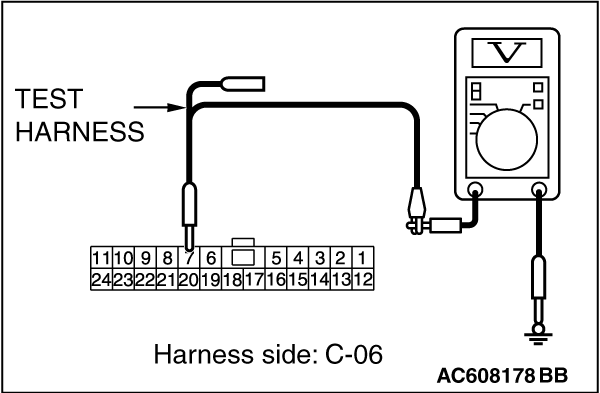
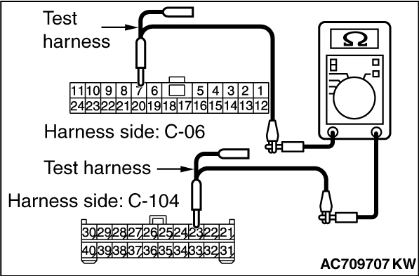
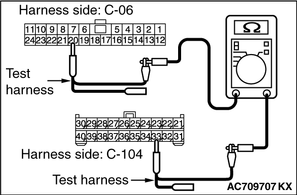
(2)Measure the resistance between joint connector (CAN1) terminal 7 and body ground.
OK: 1 kilo ohm or more
|
|
(3)Measure the resistance between joint connector (CAN1) terminal 20 and body ground.
OK: 1 kilo ohm or more
Q.
Do all the resistances measure 1 kilo ohm or more?
YES (vehicles without satellite radio) : Go to Step 12.
YES (vehicles with satellite radio) : Go to Step 11.
NO : Go to Step 55.
|
|
|
STEP 10. Check the wiring harness between joint connector (CAN1) C-06
and CAN box unit connector C-108 for a short to ground. Measure the resistance at joint connector
(CAN1) C-06.
|
|
|
(1)Disconnect joint connector (CAN1), and measure the resistance at the wiring harness
side of joint connector (CAN1).
|
|
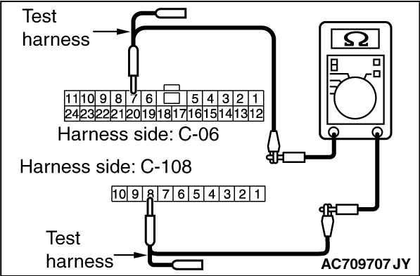
(2)Measure the resistance between joint connector (CAN1) terminal 7 and body ground.
OK: 1 kilo ohm or more
|
|
(3)Measure the resistance between joint connector (CAN1) terminal 20 and body ground.
OK: 1 kilo ohm or more
Q.
Do all the resistances measure 1 kilo ohm or more?
YES (vehicles without satellite radio) : Go to Step 12.
YES (vehicles with satellite radio) : Go to Step 11.
NO : Go to Step 56.
|
|
|
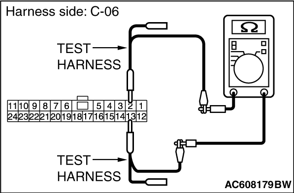
STEP 11. Check the wiring harness between joint connector (CAN1) C-06
and satellite radio tuner connector C-17 for a short to ground. Measure the resistance at joint connector
(CAN1) C-06.
|
|
|
(1)Disconnect joint connector (CAN1), and measure the resistance at the wiring harness
side of joint connector (CAN1).
|
|
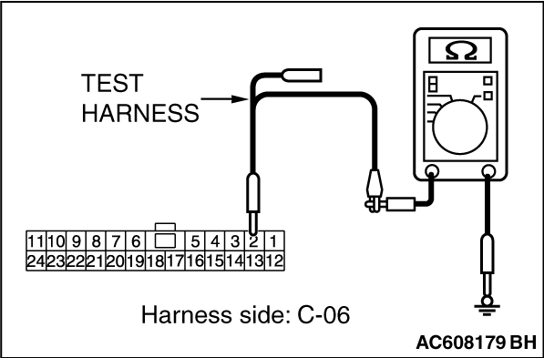
(2)Measure the resistance between joint connector (CAN1) terminal 2 and body ground.
OK: 1 kilo ohm or more
|
|
(3)Measure the resistance between joint connector (CAN1) terminal 13 and body ground.
OK: 1 kilo ohm or more
Q.
Do all the resistances measure 1 kilo ohm or more?
Go to Step 12.
Go to Step 57.
|
|
|
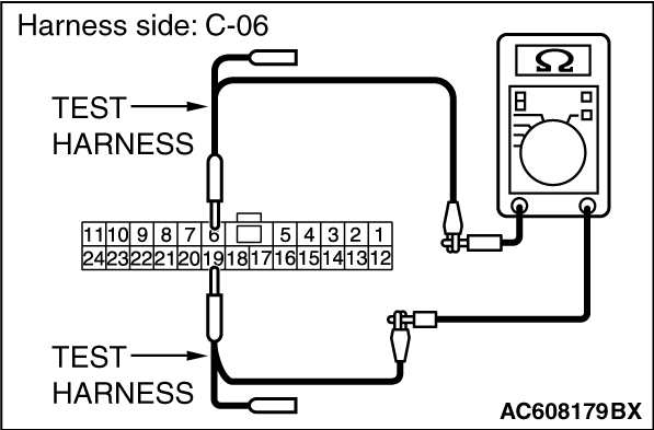
STEP 12. Check the wiring harness between joint connector (CAN1) C-06
and ETACS-ECU connector C-301 for a short to ground. Measure the resistance at joint connector
(CAN1) C-06.
|
|
|
(1)Disconnect joint connector (CAN1) and ETACS-ECU connector C-301, and measure the
resistance at the wiring harness side of joint connector (CAN1).
|
|
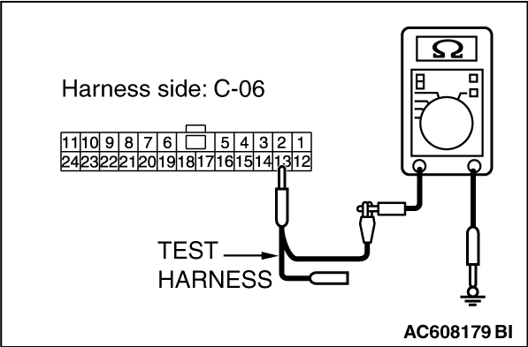
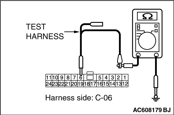
(2)Measure the resistance between joint connector (CAN1) terminal 6 and body ground.
OK: 1 kilo ohm or more
|
|
(3)Measure the resistance between joint connector (CAN1) terminal 19 and body ground.
OK: 1 kilo ohm or more
Q.
Do all the resistances measure 1 kilo ohm or more?
Go to Step 58.
Repair the wiring harness between joint connector (CAN1) C-06 and ETACS-ECU connector
C-301.
|
|
|
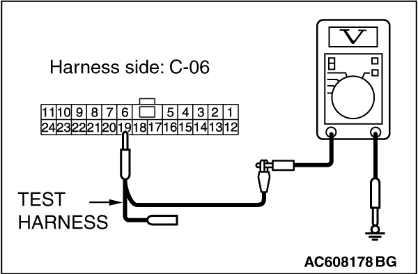
STEP 13. Check the wiring harness between ETACS-ECU connector C-301
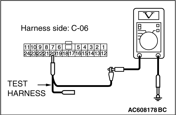
and body ground for a short to power supply. Measure the voltage at ETACS-ECU connector C-301.
|
|
|
(1)Disconnect ETACS-ECU connector C-301, and measure the voltage at the wiring harness
side of ETACS-ECU connector.
|
|
|
(2)Turn the ignition switch to the ON position.
|
|
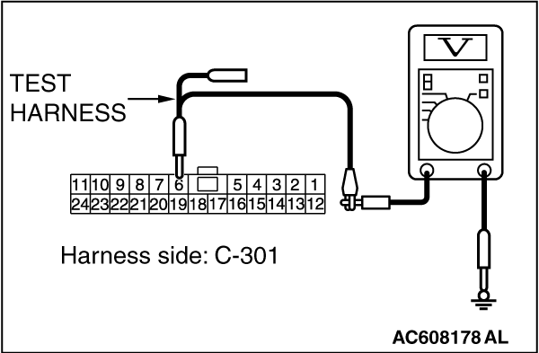
(3)Measure the voltage between ETACS-ECU connector terminal 6 and body ground.
OK: 4.7 volts or less
|
|
(4)Measure the voltage between ETACS-ECU connector terminal 7 and body ground.
OK: 4.7 volts or less
Q.
Do all the voltages measure 4.7 volts or less?
Go to Step 25.
Go to Step 14.
|
|
|
STEP 14. Check the wiring harness between joint connector (CAN1) C-06
and combination meter connector C-04 for a short to power supply. Measure the voltage at joint
connector (CAN1) C-06.
|
|
|
(1)Disconnect joint connector (CAN1), and measure the voltage at the wiring harness
side of joint connector (CAN1).
|
|
|
(2)Connect the negative battery terminal.
|
|
|
(3)Turn the ignition switch to the ON position.
|
|
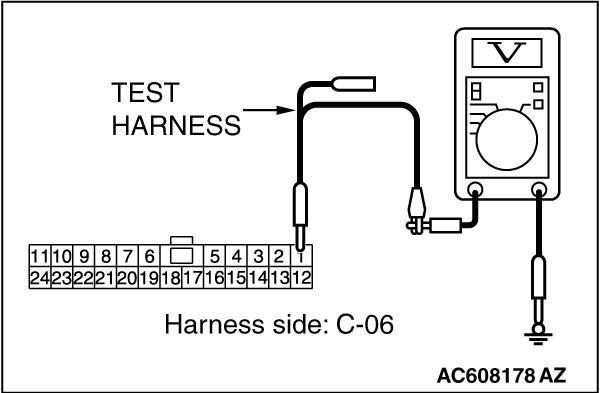
(4)Measure the voltage between joint connector (CAN1) terminal 3 and body ground.
OK: 4.7 volts or less
|
|
(5)Measure the voltage between joint connector (CAN1) terminal 14 and body ground.
OK: 4.7 volts or less
Q.
Do all the voltages measure 4.7 volts or less?
YES (vehicles with KOS) : Go to Step 15.
YES (vehicles with WCM) : Go to Step 16.
NO (vehicles with KOS and WCM) : Go to Step 48.
|
|
|
STEP 15. Check the wiring harness between joint connector (CAN1) C-06
and KOS-ECU connector C-31 for a short to power supply. Measure the voltage at joint connector
(CAN1) C-06.
|
|
|
(1)Disconnect joint connector (CAN1), and measure the voltage at the wiring harness
side of joint connector (CAN1).
|
|
|
(2)Turn the ignition switch to the ON position.
|
|
(3)Measure the voltage between joint connector (CAN1) terminal 9 and body ground.
OK: 4.7 volts or less
|
|
(4)Measure the voltage between joint connector (CAN1) terminal 22 and body ground.
OK: 4.7 volts or less
Q.
Do all the voltages measure 4.7 volts or less?
Go to Step 17.
Go to Step 49.
|
|
|
STEP 16. Check the wiring harness between joint connector (CAN1) C-06
and WCM connector C-09 for a short to power supply. Measure the voltage at joint connector (CAN1)
C-06.
|
|
|
(1)Disconnect joint connector (CAN1), and measure the voltage at the wiring harness
side of joint connector (CAN1).
|
|
|
(2)Turn the ignition switch to the ON position.
|
|
(3)Measure the voltage between joint connector (CAN1) terminal 5 and body ground.
OK: 4.7 volts or less
|
|
(4)Measure the voltage between joint connector (CAN1) terminal 16 and body ground.
OK: 4.7 volts or less
Q.
Do all the voltages measure 4.7 volts or less?
Go to Step 17.
Go to Step 50.
|
|
|
STEP 17. Check the wiring harness between joint connector (CAN1) C-06
and SRS-ECU connector C-122 for a short to power supply. Measure the voltage at joint connector
(CAN1) C-06.
|
|
|
(1)Disconnect joint connector (CAN1), and measure the voltage at the wiring harness
side of joint connector (CAN1).
|
|
|
(2)Turn the ignition switch to the ON position.
|
|
(3)Measure the voltage between joint connector (CAN1) terminal 8 and body ground.
OK: 4.7 volts or less
|
|
(4)Measure the voltage between joint connector (CAN1) terminal 21 and body ground.
OK: 4.7 volts or less
Q.
Do all the voltages measure 4.7 volts or less?
Go to Step 18.
Go to Step 51.
|
|
|
STEP 18. Check the wiring harness between joint connector (CAN1) C-06
and occupant classification-ECU connector D-35-2 for a short to power supply. Measure the voltage
at joint connector (CAN1) C-06.
|
|
|
(1)Disconnect joint connector (CAN1), and measure the voltage at the wiring harness
side of joint connector (CAN1).
|
|
|
(2)Turn the ignition switch to the ON position.
|
|
(3)Measure the voltage between joint connector (CAN1) terminal 11 and body ground.
OK: 4.7 volts or less
|
|
(4)Measure the voltage between joint connector (CAN1) terminal 24 and body ground.
OK: 4.7 volts or less
Q.
Do all the voltages measure 4.7 volts or less?
YES (vehicles without hands free system) : Go to Step 20.
YES (vehicles with hands free system) : Go to Step 19.
NO : Go to Step 52.
|
|
|
STEP 19. Check the wiring harness between joint connector (CAN1) C-06
and hands free module connector C-110 for a short to power supply. Measure the voltage at joint
connector (CAN1) C-06.
|
|
|
(1)Disconnect joint connector (CAN1), and measure the voltage at the wiring harness
side of joint connector (CAN1).
|
|
|
(2)Turn the ignition switch to the ON position.
|
|
(3)Measure the voltage between joint connector (CAN1) terminal 10 and body ground.
OK: 4.7 volts or less
|
|
(4)Measure the voltage between joint connector (CAN1) terminal 23 and body ground.
OK: 4.7 volts or less
Q.
Do all the voltages measure 4.7 volts or less?
Go to Step 20.
Go to Step 53.
|
|
|
STEP 20. Check the wiring harness between joint connector (CAN1) C-06
and A/C-ECU connector C-20 <vehicles with A/C> or heater control unit connector
C-48 <vehicles without A/C> for a short to power supply. Measure the voltage at joint connector
(CAN1) C-06.
|
|
|
(1)Disconnect joint connector (CAN1), and measure the voltage at the wiring harness
side of joint connector (CAN1).
|
|
|
(2)Turn the ignition switch to the ON position.
|
|
(3)Measure the voltage between joint connector (CAN1) terminal 1 and body ground.
OK: 4.7 volts or less
|
|
(4)Measure the voltage between joint connector (CAN1) terminal 12 and body ground.
OK: 4.7 volts or less
Q.
Do all the voltages measure 4.7 volts or less?
YES (vehicles without MMCS) : Go to Step 21.
YES (vehicles with MMCS) : Go to Step 22.
NO : Go to Step 54.
|
|
|
STEP 21. Check the wiring harness between joint connector (CAN1) C-06
and radio and CD player or CD changer connector C-104 for a short to power supply. Measure the
voltage at joint connector (CAN1) C-06.
|
|
|
(1)Disconnect joint connector (CAN1), and measure the voltage at the wiring harness
side of joint connector (CAN1).
|
|
|
(2)Turn the ignition switch to the ON position.
|
|
(3)Measure the voltage between joint connector (CAN1) terminal 7 and body ground.
OK: 4.7 volts or less
|
|
(4)Measure the voltage between joint connector (CAN1) terminal 20 and body ground.
OK: 4.7 volts or less
Q.
Do all the voltages measure 4.7 volts or less?
YES (vehicles without satellite radio) : Go to Step 24.
YES (vehicles with satellite radio) : Go to Step 23.
NO : Go to Step 55.
|
|
|
STEP 22. Check the wiring harness between joint connector (CAN1) C-06
and CAN box unit connector C-108 for a short to power supply. Measure the voltage at joint connector
(CAN1) C-06.
|
|
|
(1)Disconnect joint connector (CAN1), and measure the voltage at the wiring harness
side of joint connector (CAN1).
|
|
|
(2)Turn the ignition switch to the ON position.
|
|
(3)Measure the voltage between joint connector (CAN1) terminal 7 and body ground.
OK: 4.7 volts or less
|
|
(4)Measure the voltage between joint connector (CAN1) terminal 20 and body ground.
OK: 4.7 volts or less
Q.
Do all the voltages measure 4.7 volts or less?
YES (vehicles without satellite radio) : Go to Step 24.
YES (vehicles with satellite radio) : Go to Step 23.
NO : Go to Step 56.
|
|
|
STEP 23. Check the wiring harness between joint connector (CAN1) C-06
and satellite radio tuner connector C-17 for a short to power supply. Measure the voltage at joint
connector (CAN1) C-06.
|
|
|
(1)Disconnect joint connector (CAN1), and measure the voltage at the wiring harness
side of joint connector (CAN1).
|
|
|
(2)Turn the ignition switch to the ON position.
|
|
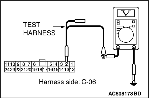
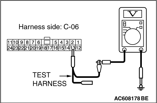
(3)Measure the voltage between joint connector (CAN1) terminal 2 and body ground.
OK: 4.7 volts or less
|
|
(4)Measure the voltage between joint connector (CAN1) terminal 13 and body ground.
OK: 4.7 volts or less
Q.
Do all the voltages measure 4.7 volts or less?
Go to Step 24.
Go to Step 57.
|
|
|
STEP 24. Check the wiring harness between joint connector (CAN1) C-06
and ETACS-ECU connector C-301 for a short to power supply. Measure the voltage at joint connector
(CAN1) C-06.
|
|
|
(1)Disconnect joint connector (CAN1), and measure the voltage at the wiring harness
side of joint connector (CAN1).
|
|
|
(2)Turn the ignition switch to the ON position.
|
|
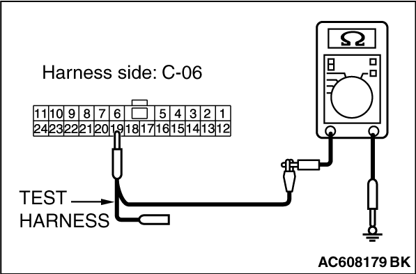
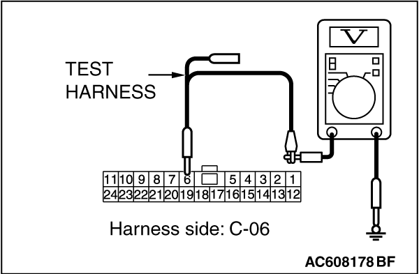
(3)Measure the voltage between joint connector (CAN1) terminal 6 and body ground.
OK: 4.7 volts or less
|
|
(4)Measure the voltage between joint connector (CAN1) terminal 19 and body ground.
OK: 4.7 volts or less
Q.
Do all the voltages measure 4.7 volts or less?
Go to Step 58.
Repair the wiring harness between joint connector (CAN1) C-06 and ETACS-ECU connector
C-301.
|
|
|
STEP 25. Check the wiring harness for line-to-line short. Measure
the resistance at ETACS-ECU connector C-301
|
|
|
| caution |
Disconnect the negative battery terminal. For details refer to .
|
|
|
|
(1)Disconnect ETACS-ECU connector C-301, and check that there is continuity at the
harness side of ETACS-ECU.
|
|
(2)Check that there is continuity between ETACS-ECU connector terminals 6 and 7.
OK: No continuity
Q.
Is the check result normal?
Go to Step 37.
Go to Step 26.
|
|
|
STEP 26. Check the wiring harness between joint connector (CAN1) C-06
and combination meter connector C-04 for line-to-line short. Measure the resistance at joint connector
(CAN1) C-06.
|
|
|
(1)Disconnect joint connector (CAN1), and check that there is continuity at the harness
side of joint connector (CAN1).
|
|
(2)Check that there is continuity between joint connector (CAN1) terminals 3 and 14.
OK: No continuity
Q.
Is the check result normal?
YES (vehicles with KOS) : Go to Step 27.
YES (vehicles with WCM) : Go to Step 28.
NO (vehicles with KOS or WCM) : Go to Step 48.
|
|
|
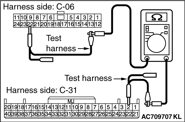
STEP 27. Check the wiring harness between joint connector (CAN1) C-06
and KOS-ECU connector C-31 for line-to-line short. Measure the resistance at joint connector
(CAN1) C-06.
|
|
|
(1)Disconnect joint connector (CAN1), and check that there is continuity at the harness
side of joint connector (CAN1).
|
|
(2)Check that there is continuity between joint connector (CAN1) terminals 9 and 22.
OK: No continuity
Q.
Is the check result normal?
Go to Step 29.
Go to Step 49.
|
|
|
STEP 28. Check the wiring harness between joint connector (CAN1) C-06
and WCM connector C-09 for line-to-line short. Measure the resistance at joint connector (CAN1)
C-06.
|
|
|
(1)Disconnect joint connector (CAN1), and check that there is continuity at the harness
side of joint connector (CAN1).
|

|
(2)Check that there is continuity between joint connector (CAN1) terminals 5 and 16.
OK: No continuity
Q.
Is the check result normal?
Go to Step 29.
Go to Step 50.
|
|
|
STEP 29. Check the wiring harness between joint connector (CAN1) C-06
and SRS-ECU connector C-122 for line-to-line short. Measure the resistance at joint connector
(CAN1) C-06.
|
|
|
(1)Disconnect joint connector (CAN1), and check that there is continuity at the harness
side of joint connector (CAN1).
|
|
(2)Check that there is continuity between joint connector (CAN1) terminals 8 and 21.
OK: No continuity
Q.
Is the check result normal?
Go to Step 30.
Go to Step 51.
|
|
|
STEP 30. Check the wiring harness between joint connector (CAN1) C-06
and occupant classification-ECU connector D-35-2 for line-to-line short. Measure the resistance
at joint connector (CAN1) C-06.
|
|
|
(1)Disconnect joint connector (CAN1), and check that there is continuity at the harness
side of joint connector (CAN1).
|
|
(2)Check that there is continuity between joint connector (CAN1) terminals 11 and 24.
OK: No continuity
Q.
Is the check result normal?
YES (vehicles without hands free system) : Go to Step 32.
YES (vehicles with hands free system) : Go to Step 31.
NO : Go to Step 52.
|
|
|
STEP 31. Check the wiring harness between joint connector (CAN1) C-06
and hands free module connector C-110 for line-to-line short. Measure the resistance at joint connector
(CAN1) C-06.
|
|
|
(1)Disconnect joint connector (CAN1), and check that there is continuity at the harness
side of joint connector (CAN1).
|
|
(2)Check that there is continuity between joint connector (CAN1) terminals 10 and 23.
OK: No continuity
Q.
Is the check result normal?
Go to Step 32.
Go to Step 53.
|
|
|
STEP 32. Check the wiring harness between joint connector (CAN1) C-06
and A/C-ECU connector C-20 <vehicles with A/C> or heater control unit connector
C-48 <vehicles without A/C> for line-to-line short. Measure the resistance at joint connector
(CAN1) C-06.
|
|
|
(1)Disconnect joint connector (CAN1), and check that there is continuity at the harness
side of joint connector (CAN1).
|
|
(2)Check that there is continuity between joint connector (CAN1) terminals 1 and 12.
OK: No continuity
Q.
Is the check result normal?
YES (vehicles without MMCS) : Go to Step 33.
YES (vehicles with MMCS) : Go to Step 34.
NO : Go to Step 54.
|
|
|
STEP 33. Check the wiring harness between joint connector (CAN1) C-06
and radio and CD player or CD changer connector C-104 for line-to-line short. Measure the resistance
at joint connector (CAN1) C-06.
|
|
|
(1)Disconnect joint connector (CAN1), and check that there is continuity at the harness
side of joint connector (CAN1).
|
|
(2)Check that there is continuity between joint connector (CAN1) terminals 7 and 20.
OK: No continuity
Q.
Is the check result normal?
YES (vehicles without satellite radio) : Go to Step 36.
YES (vehicles with satellite radio) : Go to Step 35.
NO : Go to Step 55.
|
|
|
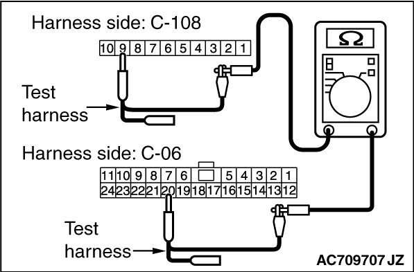
STEP 34. Check the wiring harness between joint connector (CAN1) C-06
and CAN box unit connector C-108 for line-to-line short. Measure the resistance at joint connector
(CAN1) C-06.
|
|
|
(1)Disconnect joint connector (CAN1), and check that there is continuity at the harness
side of joint connector (CAN1).
|
|
(2)Check that there is continuity between joint connector (CAN1) terminals 7 and 20.
OK: No continuity
Q.
Is the check result normal?
YES (vehicles without satellite radio) : Go to Step 36.
YES (vehicles with satellite radio) : Go to Step 35.
NO : Go to Step 56.
|
|
|
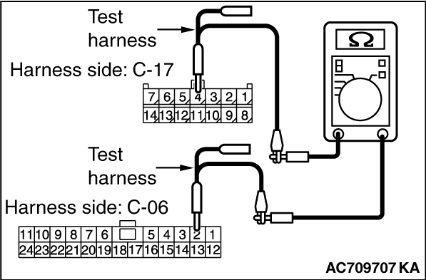
STEP 35. Check the wiring harness between joint connector (CAN1) C-06
and satellite radio tuner connector C-17 for line-to-line short. Measure the resistance at joint connector
(CAN1) C-06.
|
|
|
(1)Disconnect joint connector (CAN1), and check that there is continuity at the harness
side of joint connector (CAN1).
|
|
(2)Check that there is continuity between joint connector (CAN1) terminals 2 and 13.
OK: No continuity
Q.
Is the check result normal?
Go to Step 36.
Go to Step 57.
|
|
|
STEP 36. Check the wiring harness between joint connector (CAN1) C-06
and EATCS-ECU connector C-301 for line-to-line short. Measure the resistance at joint connector
(CAN1) C-06.
|
|
|
(1)Disconnect joint connector (CAN1) and ETACS-ECU connector C-301, and check that
there is continuity at the harness side of joint connector (CAN1).
|
|
(2)Check that there is continuity between joint connector (CAN1) terminals 6 and 19.
OK: No continuity
Q.
Is the check result normal?
Go to Step 58.
Repair the wiring harness between joint connector (CAN1) C-06 and ETACS-ECU connector
C-301.
|
|
|
STEP 37. Check the wiring harness between joint connector (CAN1) C-06
and combination meter connector C-04 for open circuit.
|
|
|
| caution |
Strictly observe the specified wiring harness repair procedure.
For details refer to .
|
|
|
|
(1)Disconnect joint connector (CAN1) C-06 and combination meter connector C-301, and
check the wiring harness.
|
|
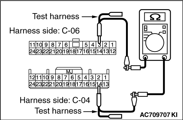
(2)Check the wiring harness between joint connector (CAN1) C-06 (terminal 3) and combination
meter connector C-04 (terminal 14)
OK: Continuity exists (2 Ω
or less)
|
|
(3)Check the wiring harness between joint connector (CAN1) C-06 (terminal 14) and combination
meter connector C-04 (terminal 15)
OK: Continuity exists (2 Ω
or less)
Q.
Is the wiring harness between joint connector (CAN1) C-06 and combination meter connector
C-04 in good condition?
YES (vehicles with KOS) : Go to Step 38.
YES (vehicles with WCM) : Go to Step 39.
NO ((vehicles with KOS or WCM) : Go to Step 48.
|
|
|
STEP 38. Check the wiring harness between joint connector (CAN1) C-06
and KOS-ECU connector C-31 for open circuit.
|
|
|
(1)Disconnect joint connector (CAN1) C-06 and KOS-ECU connector C-31, and check the
wiring harness.
|
|
(2)Check the wiring harness between joint connector (CAN1) C-06 (terminal 9) and KOS-ECU
connector C-31 (terminal 1)
OK: Continuity exists (2 Ω
or less)
|
|
(3)Check the wiring harness between joint connector (CAN1) C-06 (terminal 22) and KOS-ECU
connector C-31 (terminal 2)
OK: Continuity exists (2 Ω
or less)
Q.
Is the wiring harness between joint connector (CAN1) C-06 and KOS-ECU connector C-31
in good condition?
Go to Step 40.
Go to Step 49.
|
|
|
STEP 39. Check the wiring harness between joint connector (CAN1) C-06
and WCM connector C-09 for open circuit.
|
|
|
(1)Disconnect joint connector (CAN1) C-06 and WCM connector C-09, and check the wiring
harness.
|
|
(2)Check the wiring harness between joint connector (CAN1) C-06 (terminal 5) and WCM connector
C-09 (terminal 11)
OK: Continuity exists (2 Ω
or less)
|
|
(3)Check the wiring harness between joint connector (CAN1) C-06 (terminal 16) and WCM connector
C-09 (terminal 10)
OK: Continuity exists (2 Ω
or less)
Q.
Is the wiring harness between joint connector (CAN1) C-06 and WCM connector C-09 in
good condition?
Go to Step 40.
Go to Step 50.
|
|
|
STEP 40. Check the wiring harness between joint connector (CAN1) C-06
and SRS-ECU connector C-122 for open circuit.
|
|
|
(1)Disconnect joint connector (CAN1) C-06 and SRS-ECU connector C-122, and check the
wiring harness.
|
|
(2)Check the wiring harness between joint connector (CAN1) C-06 (terminal 8) and SRS-ECU
connector C-122 (terminal 10)
OK: Continuity exists (2 Ω
or less)
|
|
(3)Check the wiring harness between joint connector (CAN1) C-06 (terminal 21) and SRS-ECU
connector C-122 (terminal 9)
OK: Continuity exists (2 Ω
or less)
Q.
Is the wiring harness between joint connector (CAN1) C-06 and SRS-ECU connector C-122
in good condition?
Go to Step 41.
Go to Step 51.
|
|
|
STEP 41. Check the wiring harness between joint connector (CAN1) C-06
and occupant classification-ECU connector D-35-2 for open circuit.
|
|
|
(1)Disconnect joint connector (CAN1) C-06 and occupant classification-ECU connector
D-35-2, and check the wiring harness.
|
|
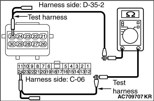
(2)Check the wiring harness between joint connector (CAN1) C-06 (terminal 11) and occupant
classification-ECU connector D-35-2 (terminal 24)
OK: Continuity exists (2 Ω
or less)
|
|
(3)Check the wiring harness between joint connector (CAN1) C-06 (terminal 24) and occupant
classification-ECU connector D-35-2 (terminal 25)
OK: Continuity exists (2 Ω
or less)
Q.
Is the wiring harness between joint connector (CAN1) C-06 and occupant classification-ECU
connector D-35-2 in good condition?
YES (vehicles without hands free system) : Go to Step 43.
YES (vehicles with hands free system) : Go to Step 42.
NO : Go to Step 52.
|
|
|
STEP 42. Check the wiring harness between joint connector (CAN1) C-06
and hands free module connector C-110 for open circuit.
|
|
|
(1)Disconnect joint connector (CAN1) C-06 and occupant hands free module connector
C-110, and check the wiring harness.
|
|
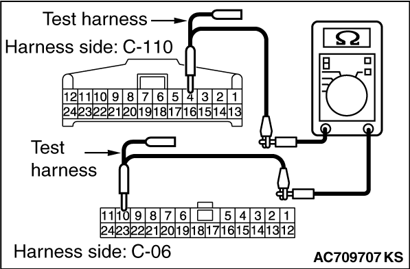
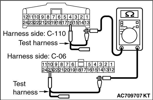
(2)Check the wiring harness between joint connector (CAN1) C-06 (terminal 10) and hands free
module connector C-110 (terminal 4)
OK: Continuity exists (2 Ω
or less)
|
|
(3)Check the wiring harness between joint connector (CAN1) C-06 (terminal 23) and hands free
module connector C-110 (terminal 16)
OK: Continuity exists (2 Ω
or less)
Q.
Is the wiring harness between joint connector (CAN1) C-06 and hands free module connector
C-110 in good condition?
Go to Step 43.
Go to Step 53.
|
|
|
STEP 43. Check the wiring harness between joint connector (CAN1) C-06
and A/C-ECU connector C-20 <vehicles with A/C> or heater control unit connector
C-48 <vehicles without A/C> for open circuit.
|
|
|
(1)Disconnect joint connector (CAN1) C-06 and A/C-ECU connector C-20 <vehicles
with A/C> or heater control unit connector C-48 <vehicles without A/C>, and check the wiring
harness.
|
|
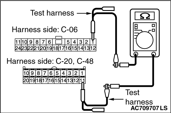
(2)Check the wiring harness between joint connector (CAN1) C-06 (terminal 1) and A/C-ECU
connector C-20 <vehicles with A/C> or heater control unit connector C-48 <vehicles without
A/C> (terminal 11)
OK: Continuity exists (2 Ω
or less)
|
|
(3)Check the wiring harness between joint connector (CAN1) C-06 (terminal 12) and A/C-ECU
connector C-20 <vehicles with A/C> or heater control unit connector C-48 <vehicles without
A/C> (terminal 12)
OK: Continuity exists (2 Ω
or less)
Q.
Is the wiring harness between joint connector (CAN1) C-06 and A/C-ECU connector
C-20 <vehicles with A/C> or heater control unit connector C-48 <vehicles without A/C>
in good condition?
YES (vehicles without MMCS) : Go to Step 44.
YES (vehicles with MMCS) : Go to Step 45.
NO : Go to Step 54.
|
|
|
STEP 44. Check the wiring harness between joint connector (CAN1) C-06
and radio and CD player or CD changer connector C-104 for open circuit.
|
|
|
(1)Disconnect joint connector (CAN1) C-06 and radio and CD player or CD changer connector
C-104, and check the wiring harness.
|
|
(2)Check the wiring harness between joint connector (CAN1) C-06 (terminal 7) and radio and
CD player or CD changer connector C-104 (terminal 23)
OK: Continuity exists (2 Ω
or less)
|
|
(3)Check the wiring harness between joint connector (CAN1) C-06 (terminal 20) and radio and
CD player or CD changer connector C-104 (terminal 33)
OK: Continuity exists (2 Ω
or less)
Q.
Is the wiring harness between joint connector (CAN1) C-06 and radio and CD player
or CD changer connector C-104 in good condition?
YES (vehicles without satellite radio) : Go to Step 47.
YES (vehicles with satellite radio) : Go to Step 46.
NO : Go to Step 55.
|
|
|
STEP 45. Check the wiring harness between joint connector (CAN1) C-06
and CAN box unit connector C-108 for open circuit.
|
|
|
(1)Disconnect joint connector (CAN1) C-06 and CAN box unit connector C-108, and check
the wiring harness.
|
|
(2)Check the wiring harness between joint connector (CAN1) C-06 (terminal 7) and CAN box
unit connector C-108 (terminal 8)
OK: Continuity exists (2 Ω
or less)
|
|
(3)Check the wiring harness between joint connector (CAN1) C-06 (terminal 20) and CAN box
unit connector C-108 (terminal 9)
OK: Continuity exists (2 Ω
or less)
Q.
Is the wiring harness between joint connector (CAN1) C-06 and CAN box unit connector
C-108 in good condition?
YES (vehicles without satellite radio) : Go to Step 47.
YES (vehicles with satellite radio) : Go to Step 46.
NO : Go to Step 56.
|
|
|
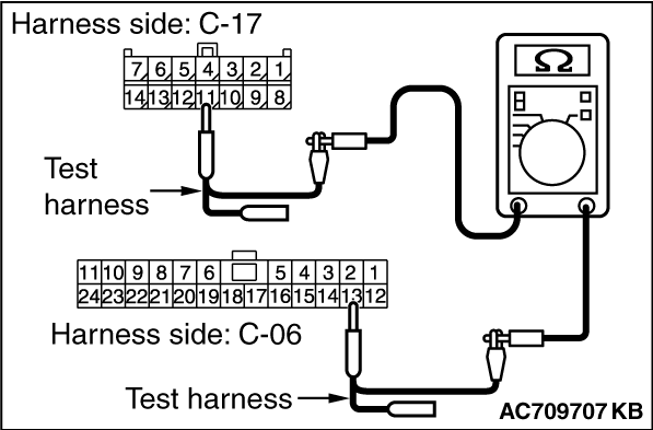
STEP 46. Check the wiring harness between joint connector (CAN1) C-06
and satellite radio tuner connector C-17 for open circuit.
|
|
|
(1)Disconnect joint connector (CAN1) C-06 and satellite radio tuner connector C-17,
and check the wiring harness.
|
|
(2)Check the wiring harness between joint connector (CAN1) C-06 (terminal 2) and satellite
radio tuner connector C-17 (terminal 4)
OK: Continuity exists (2 Ω
or less)
|
|
(3)Check the wiring harness between joint connector (CAN1) C-06 (terminal 13) and satellite
radio tuner connector C-17 (terminal 11)
OK: Continuity exists (2 Ω
or less)
Q.
Is the wiring harness between joint connector (CAN1) C-06 and satellite radio tuner
connector C-17 in good condition?
Go to Step 47.
Go to Step 57.
|
|
|
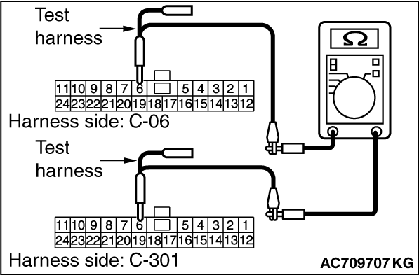
STEP 47. Check the wiring harness between joint connector (CAN1) C-06
and ETACS-ECU connector C-301 for open circuit.
|
|
|
(1)Disconnect joint connector (CAN1) C-06 and ETACS-ECU connector C-301, and check
the wiring harness.
|
|
(2)Check the wiring harness between joint connector (CAN1) C-06 (terminal 6) and ETACS-ECU
connector C-301 (terminal 6)
OK: Continuity exists (2 Ω
or less)
|
|
(3)Check the wiring harness between joint connector (CAN1) C-06 (terminal 19) and ETACS-ECU
connector C-301 (terminal 7)
OK: Continuity exists (2 Ω
or less)
Q.
Is the wiring harness between joint connector (CAN1) C-06 and ETACS-ECU connector
C-301 in good condition?
Go to Step 58.
Repair the wiring harness between joint connector (CAN1) C-06 and ETACS-ECU connector
C-301.
|
|
|
STEP 48. Using scan tool MB991958, diagnose the CAN bus line. (checking
the combination meter for internal failure)
|
|
|
| caution |
Strictly observe the specified wiring harness repair procedure.
For details refer to .
|
|
|
|
| caution |
To prevent damage to scan tool MB991958, always turn the ignition switch to
the "LOCK" (OFF) position before connecting or disconnecting scan tool MB991958.
|
|
|
|
(1)Disconnect combination meter connector C-04.
|
|
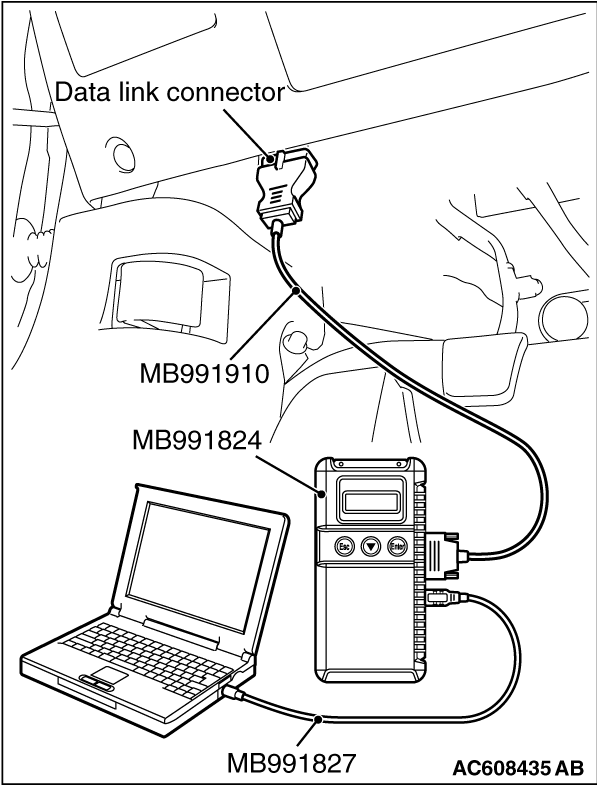
(2)Connect scan tool MB991958 to the data link connector.
(3)Turn the ignition switch to the "ON" position.
|
|
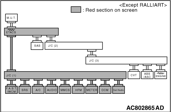
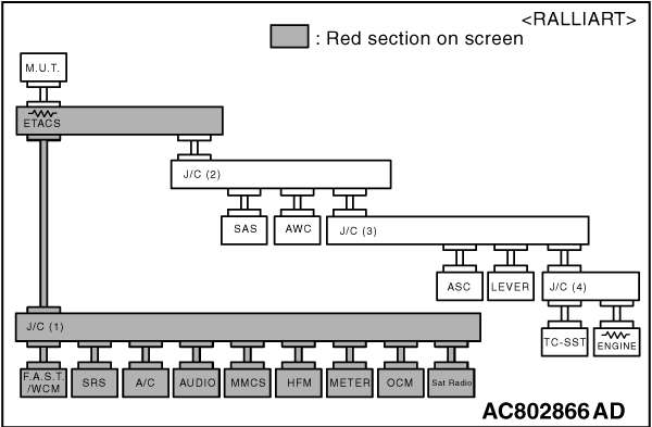
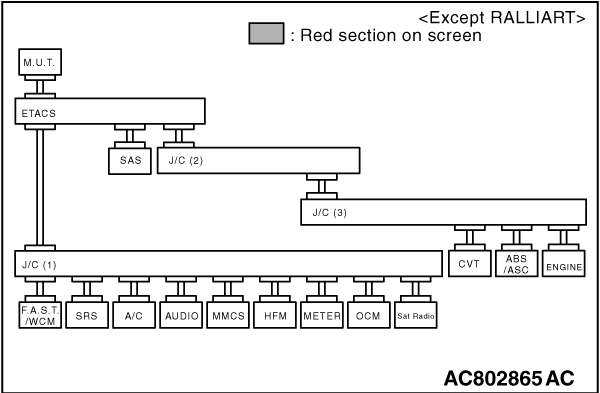
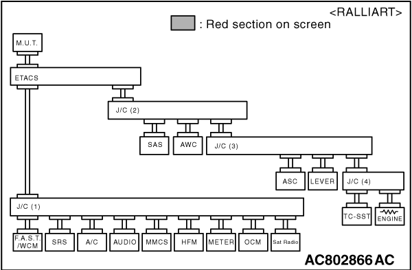
(4)Diagnose CAN bus lines, and check if the scan tool MB991958 screen is as shown in the
figure.
OK: The display of the scan tool MB991958 is as shown in the figure.
Q.
Does scan tool MB991958 screen correspond to the illustration?
Repair the wiring harness between joint connector (CAN1) C-06 and combination
meter connector C-04.
Check combination meter connector C-04, and repair if necessary. If the combination
meter connector is in good condition, replace the combination meter.
|
|
|
STEP 49. Using scan tool MB991958, diagnose the CAN bus line. (checking
the KOS-ECU for internal failure)
|
|
|
| caution |
Strictly observe the specified wiring harness repair procedure.
For details refer to .
|
|
|
|
| caution |
To prevent damage to scan tool MB991958, always turn the ignition switch to
the "LOCK" (OFF) position before connecting or disconnecting scan tool MB991958.
|
|
|
|
(1)Disconnect KOS-ECU connector C-31.
|
|
(2)Connect scan tool MB991958 to the data link connector.
(3)Turn the ignition switch to the "ON" position.
|
|
(4)Diagnose CAN bus lines, and check if the scan tool MB991958 screen is as shown in the
figure.
OK: The display of the scan tool MB991958 is as shown in the figure.
Q.
Does scan tool MB991958 screen correspond to the illustration?
Repair the wiring harness between joint connector (CAN1) C-06 and KOS-ECU connector
C-31.
Check KOS-ECU connector C-31, and repair if necessary. If the KOS-ECU connector
is in good condition, replace the KOS-ECU.
|
|
|
STEP 50. Using scan tool MB991958, diagnose the CAN bus line. (checking
the WCM for internal failure)
|
|
|
| caution |
Strictly observe the specified wiring harness repair procedure.
For details refer to .
|
|
|
|
| caution |
To prevent damage to scan tool MB991958, always turn the ignition switch to
the "LOCK" (OFF) position before connecting or disconnecting scan tool MB991958.
|
|
|
|
(1)Disconnect WCM connector C-09.
|
|
(2)Connect scan tool MB991958 to the data link connector.
(3)Turn the ignition switch to the "ON" position.
|
|
(4)Diagnose CAN bus lines, and check if the scan tool MB991958 screen is as shown in the
figure.
OK: The display of the scan tool MB991958 is as shown in the figure.
Q.
Does scan tool MB991958 screen correspond to the illustration?
Repair the wiring harness between joint connector (CAN1) C-06 and WCM connector
C-09.
Check WCM connector C-09, and repair if necessary. If the WCM connector is in
good condition, replace the WCM.
|
|
|
STEP 51. Using scan tool MB991958, diagnose the CAN bus line. (checking
the SRS-ECU for internal failure)
|
|
|
| caution |
Strictly observe the specified wiring harness repair procedure.
For details refer to .
|
|
|
|
| caution |
To prevent damage to scan tool MB991958, always turn the ignition switch to
the "LOCK" (OFF) position before connecting or disconnecting scan tool MB991958.
|
|
|
|
(1)Disconnect SRS-ECU connector C-122.
|
|
(2)Connect scan tool MB991958 to the data link connector.
(3)Turn the ignition switch to the "ON" position.
|
|
(4)Diagnose CAN bus lines, and check if the scan tool MB991958 screen is as shown in the
figure.
OK: The display of the scan tool MB991958 is as shown in the figure.
Q.
Does scan tool MB991958 screen correspond to the illustration?
Repair the wiring harness between joint connector (CAN1) C-06 and SRS-ECU connector
C-122.
Check SRS-ECU connector C-122, and repair if necessary. If the SRS-ECU connector
is in good condition, replace the SRS-ECU.
|
|
|
STEP 52. Using scan tool MB991958, diagnose the CAN bus line. (checking
the occupant classification-ECU for internal failure)
|
|
|
| caution |
Strictly observe the specified wiring harness repair procedure.
For details refer to .
|
|
|
|
| caution |
To prevent damage to scan tool MB991958, always turn the ignition switch to
the "LOCK" (OFF) position before connecting or disconnecting scan tool MB991958.
|
|
|
|
(1)Disconnect occupant classification-ECU connector D-35-2.
|
|
(2)Connect scan tool MB991958 to the data link connector.
(3)Turn the ignition switch to the "ON" position.
|
|
(4)Diagnose CAN bus lines, and check if the scan tool MB991958 screen is as shown in the
figure.
OK: The display of the scan tool MB991958 is as shown in the figure.
Q.
Does scan tool MB991958 screen correspond to the illustration?
Repair the wiring harness between joint connector (CAN1) C-06 and occupant classification-ECU connector
D-35-2.
Check occupant classification-ECU connector D-35-2, and repair if necessary. If
the occupant classification-ECU connector is in good condition, replace the occupant classification-ECU.
|
|
|
STEP 53. Using scan tool MB991958, diagnose the CAN bus line. (checking
the hands free module for internal failure)
|
|
|
| caution |
Strictly observe the specified wiring harness repair procedure.
For details refer to .
|
|
|
|
| caution |
To prevent damage to scan tool MB991958, always turn the ignition switch to
the "LOCK" (OFF) position before connecting or disconnecting scan tool MB991958.
|
|
|
|
(1)Disconnect hands free module connector C-110.
|
|
(2)Connect scan tool MB991958 to the data link connector.
(3)Turn the ignition switch to the "ON" position.
|
|
(4)Diagnose CAN bus lines, and check if the scan tool MB991958 screen is as shown in the
figure.
OK: The display of the scan tool MB991958 is as shown in the figure.
Q.
Does scan tool MB991958 screen correspond to the illustration?
Repair the wiring harness between joint connector (CAN1) C-06 and hands free module
connector C-110.
Check hands free module connector C-110, and repair if necessary. If the hands
free module connector is in good condition, replace the hands free module.
|
|
|
STEP 54. Using scan tool MB991958, diagnose the CAN bus line. (checking
the A/C-ECU <vehicles with A/C> or heater control unit <vehicles without A/C>
for internal failure)
|
|
|
| caution |
Strictly observe the specified wiring harness repair procedure.
For details refer to .
|
|
|
|
| caution |
To prevent damage to scan tool MB991958, always turn the ignition switch to
the "LOCK" (OFF) position before connecting or disconnecting scan tool MB991958.
|
|
|
|
(1)Disconnect A/C-ECU connector C-20 <vehicles with A/C> or heater control
unit connector C-48 <vehicles without A/C>.
|
|
(2)Connect scan tool MB991958 to the data link connector.
(3)Turn the ignition switch to the "ON" position.
|
|
(4)Diagnose CAN bus lines, and check if the scan tool MB991958 screen is as shown in the
figure.
OK: The display of the scan tool MB991958 is as shown in the figure.
Q.
Does scan tool MB991958 screen correspond to the illustration?
Repair the wiring harness between joint connector (CAN1) C-06 and A/C-ECU
connector C-20 <vehicles with A/C> or heater control unit connector C-48 <vehicles without
A/C>.
Check A/C-ECU connector C-20 <vehicles with A/C> or heater control
unit connector C-48 <vehicles without A/C>, and repair if necessary. If the A/C-ECU <vehicles
with A/C> or heater control unit <vehicles without A/C> connector is in good condition,
replace the A/C-ECU <vehicles with A/C> or heater control unit <vehicles without
A/C>.
|
|
|
STEP 55. Using scan tool MB991958, diagnose the CAN bus line. (checking
the radio and CD player or CD changer for internal failure)
|
|
|
| caution |
Strictly observe the specified wiring harness repair procedure.
For details refer to .
|
|
|
|
| caution |
To prevent damage to scan tool MB991958, always turn the ignition switch to
the "LOCK" (OFF) position before connecting or disconnecting scan tool MB991958.
|
|
|
|
(1)Disconnect radio and CD player or CD changer connector C-104.
|
|
(2)Connect scan tool MB991958 to the data link connector.
(3)Turn the ignition switch to the "ON" position.
|
|
(4)Diagnose CAN bus lines, and check if the scan tool MB991958 screen is as shown in the
figure.
OK: The display of the scan tool MB991958 is as shown in the figure.
Q.
Does scan tool MB991958 screen correspond to the illustration?
Repair the wiring harness between joint connector (CAN1) C-06 and radio and CD
player or CD changer connector C-104.
Check radio and CD player or CD changer connector C-104, and repair if necessary.
If the radio and CD player or CD changer connector is in good condition, replace the radio and
CD player or CD changer.
|
|
|
STEP 56. Using scan tool MB991958, diagnose the CAN bus line. (checking
the CAN box unit for internal failure)
|
|
|
| caution |
Strictly observe the specified wiring harness repair procedure.
For details refer to .
|
|
|
|
| caution |
To prevent damage to scan tool MB991958, always turn the ignition switch to
the "LOCK" (OFF) position before connecting or disconnecting scan tool MB991958.
|
|
|
|
(1)Disconnect CAN box unit connector C-108.
|
|
(2)Connect scan tool MB991958 to the data link connector.
(3)Turn the ignition switch to the "ON" position.
|
|
(4)Diagnose CAN bus lines, and check if the scan tool MB991958 screen is as shown in the
figure.
OK: The display of the scan tool MB991958 is as shown in the figure.
Q.
Does scan tool MB991958 screen correspond to the illustration?
Repair the wiring harness between joint connector (CAN1) C-06 and CAN box unit
connector C-108.
Check CAN box unit connector C-108, and repair if necessary. If the CAN box unit
connector is in good condition, replace the CAN box unit.
|
|
|
STEP 57. Using scan tool MB991958, diagnose the CAN bus line. (checking
the satellite radio tuner for internal failure)
|
|
|
| caution |
Strictly observe the specified wiring harness repair procedure.
For details refer to .
|
|
|
|
| caution |
To prevent damage to scan tool MB991958, always turn the ignition switch to
the "LOCK" (OFF) position before connecting or disconnecting scan tool MB991958.
|
|
|
|
(1)Disconnect satellite radio tuner connector C-17.
|
|
(2)Connect scan tool MB991958 to the data link connector.
(3)Turn the ignition switch to the "ON" position.
|
|
(4)Diagnose CAN bus lines, and check if the scan tool MB991958 screen is as shown in the
figure.
OK: The display of the scan tool MB991958 is as shown in the figure.
Q.
Does scan tool MB991958 screen correspond to the illustration?
Repair the wiring harness between joint connector (CAN1) C-06 and satellite radio
tuner connector C-17.
Check satellite radio tuner connector C-17, and repair if necessary. If the satellite
radio tuner connector is in good condition, replace the satellite radio tuner.
|
|
|
STEP 58. Using scan tool MB991958, diagnose the CAN bus line. (trouble
symptom check)
|
|
|
| caution |
Strictly observe the specified wiring harness repair procedure.
For details refer to .
|
|
|
|
| caution |
To prevent damage to scan tool MB991958, always turn the ignition switch to
the "LOCK" (OFF) position before connecting or disconnecting scan tool MB991958.
|
|
|
(1)Connect scan tool MB991958 to the data link connector.
(2)Turn the ignition switch to the "ON" position.
|
|
(3)Diagnose CAN bus lines, and check if the scan tool MB991958 screen is as shown in the
figure.
OK: The display of the scan tool MB991958 is as shown in the figure.
Q.
Does scan tool MB991958 screen correspond to the illustration?
The trouble can be an intermittent malfunction (Refer to GROUP 00, How to use
Troubleshooting/inspection Service Points -
How to Cope with Intermittent
Malfunction ).
Check the ETACS-ECU connector C-301, and repair if necessary. If the ETACS-ECU
connector is in good condition, replace the ETACS-ECU.
|
)
)
)
)
)
)
)
)
)
)
)
)
)
)
)
)
)
)
)
)
)
)
)
)
)
)
)
)
)
)
)
)
)
)
)
)
)
)
)
)
)
)
)
)
)
)
)
)
)
)
)
)
)
)
)
)
)
)
)
)
)
)
)
)
)
)
)
)
)
)
)
)
)
)
)
)
)
)
)
)
)
)
)
)
)
)
)