![[Previous]](../../../buttons/fprev.png)
![[Next]](../../../buttons/fnext.png)
DIAGNOSTIC ITEM
1: Diagnose when the scan tool cannot receive the data sent by ETACS-ECU.
| caution |
When servicing a CAN bus line, ground yourself by
touching a metal object such as an unpainted water pipe. If you fail to do so, a component connected
to the CAN bus line may be damaged.
|

FUNCTION
When the CAN bus diagnosis is carried out, the scan tool communicates with the ETACS-ECU.
If a communication flag is not set for the ETACS-ECU, the ETACS-ECU will be diagnosed as a communication
error.
TROUBLE JUDGEMENT CONDITIONS
If a communication flag is not set for the ETACS-ECU, the ETACS-ECU determines that there
is a failure.
TROUBLESHOOTING HINTS
- Malfunction of the connector (data link connector or ETACS-ECU connector
improperly connected)
- Malfunction of the wiring harness (open circuit, short to ground, short to power
supply between the data link connector and the ETACS-ECU connector, line-to-line short, or power
supply to the ETACS-ECU)
- Malfunction of ETACS-ECU
|
|
Required Special Tools:
- MB991223: Harness Set
- MB992006: Extra Fine Probe
- MB991958: Scan Tool (M.U.T.-III Sub Assembly)
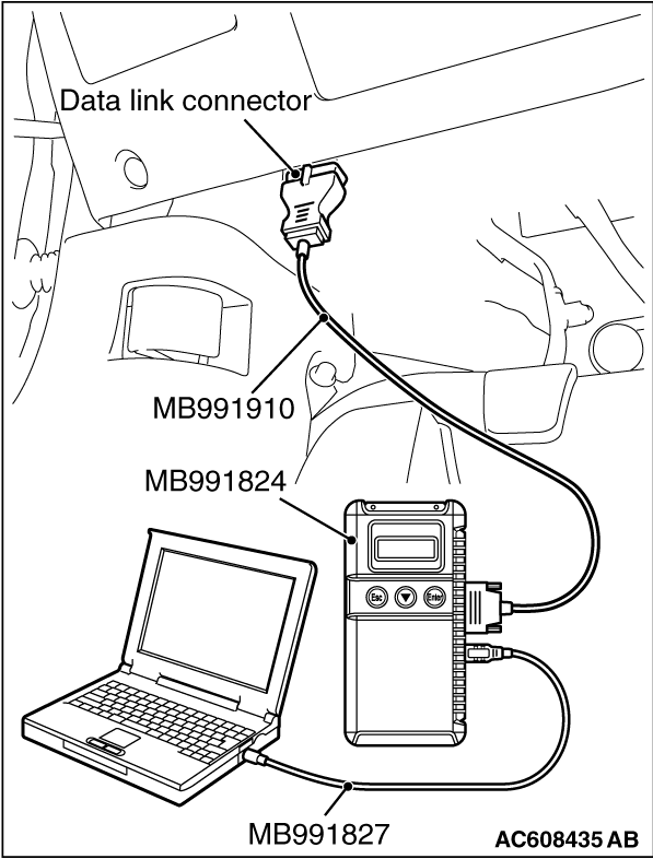
- MB991824: Vehicle Communication Interface (V.C.I.)
- MB991827: M.U.T.-III USB Cable
- MB991910: M.U.T.-III Main Harness A
|
|
|
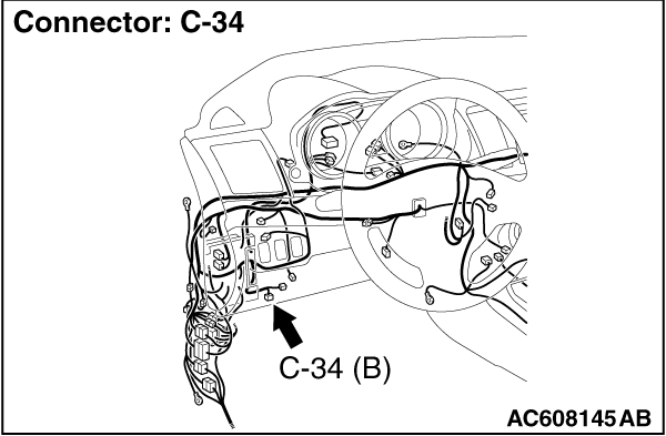
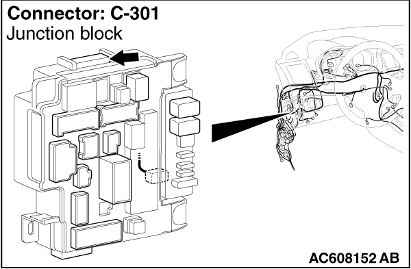
STEP 1. Check data link connector C-34 and ETACS-ECU connector
C-301 for loose, corroded or damaged terminals, or terminals pushed back in the connector.
|
|
|
| caution |
The strand end of the twisted wire should be within 10 cm (4
inches) from the connector. For details refer to  . .
|
|
|
|
Q.
Are data link connector C-34 and ETACS-ECU connector C-301 in good condition?
|
|
|
 Go to Step 2. Go to Step 2.
|
|
|
|
|
|
 Repair the damaged parts. Repair the damaged parts.
|
|
|
|
|
|
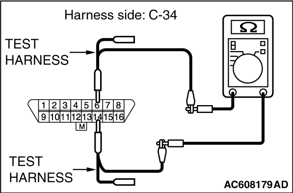
STEP 2. Check the wiring harness between data link connector C-34
and ETACS-ECU connector C-301 for open circuit.
|
|
|
| caution |
Strictly observe the specified wiring harness repair procedure.
For details refer to .
|
|
|
|
(1)Disconnect the scan tool and ETACS-ECU connector C-301, and check the wiring harness.
|

|
(2)Check the wiring harness between data link connector C-34 (terminal 6) and ETACS-ECU connector
C-301 (terminal 5) <CAN_H>
OK: Continuity exists (2 Ω or less)
|

|
(3)Check the wiring harness between data link connector C-34 (terminal 14) and ETACS-ECU
connector C-301 (terminal 4) <CAN_L>
OK: Continuity exists (2 Ω or less)
Q.
Is the wiring harness between data link connector C-34 and ETACS-ECU connector C-301
in good condition?
Go to Step 3.
Repair the wiring harness between data link connector C-34 and ETACS-ECU connector
C-301.
|
|
|
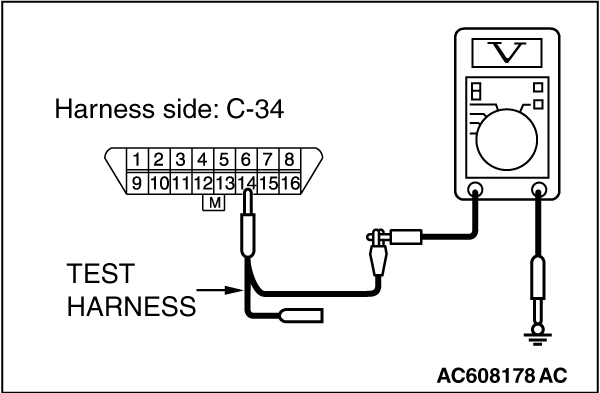
STEP 3. Check the wiring harness between data link connector C-34
and ETACS-ECU connector C-301 for a short to ground. Measure the resistance at data link connector
C-34.
|
|
|
| caution |
Disconnect the negative battery terminal. For details refer to .
|
|
|
|
| caution |
A digital multimeter should be used. For details refer to .
|
|
|
|
| caution |
The test wiring harness should be used. For details refer to .
|
|
|
|
(1)Disconnect the scan tool and ETACS-ECU connector C-301, and measure the resistance
at the wiring harness side of data link connector C-34.
|

|
(2)Measure the resistance between data link connector terminal 6 and body ground. <CAN_H>
OK: 1 kilo ohm or more
|

|
(3)Measure the resistance between data link connector terminal 14 and body ground. <CAN_L>
OK: 1 kilo ohm or more
Q.
Do all the resistances measure 1 kilo ohm or more?
Go to Step 4.
Repair the wiring harness between data link connector C-34 and ETACS-ECU connector
C-301.
|
|
|
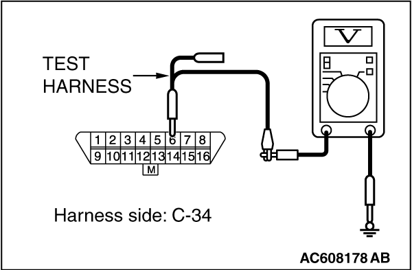
STEP 4. Check the wiring harness between data link connector C-34
and ETACS-ECU connector C-301 for a short to the power supply. Measure the voltage at data link connector
C-34.
|
|
|
(1)Disconnect the scan tool and ETACS-ECU connector C-301, and measure the resistance
at the wiring harness side of data link connector C-34.
|
|
|
(2)Turn the ignition switch to the "ON" position.
|
|
(3)Measure the voltage between data link connector terminal 6 and body ground. <CAN_H>
OK: 5 volts or less
|
|
(4)Measure the voltage between data link connector terminal 14 and body ground. <CAN_L>
OK: 5 volts or less
Q.
Do all the voltage measure 5 volts or less?
Go to Step 5.
Repair the wiring harness between data link connector C-34 and ETACS-ECU connector
C-301.
|
|
|
STEP 5. Check the wiring harness between data link connector C-34
and ETACS-ECU connector C-301 for line-to-line short. Measure the resistance at data link connector C-34.
|
|
|
(1)Disconnect the scan tool and ETACS-ECU connector C-301, and measure the resistance
at the wiring harness side of data link connector C-34.
|
|
(2)Measure the resistance between data link connector terminal 6 and 14.
OK: No continuity
Q.
Is the check result normal?
Go to Step 6.
Repair the wiring harness between data link connector C-34 and ETACS-ECU connector
C-301.
|
|
|
STEP 6. Using scan tool MB991958, diagnose the CAN bus line.
|
|
(1)
| caution |
To prevent damage to scan tool MB991958, always turn the ignition switch
to the "LOCK" (OFF) position before connecting or disconnecting scan tool MB991958.
|
Connect scan tool MB991958 to the data link connector.
(2)Turn the ignition switch to the "ON" position.
|
|
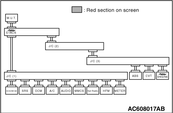
(3)Diagnose CAN bus lines, and check if the scan tool screen is as shown in the illustration.
Q.
Does the scan tool screen correspond to the illustration?
The trouble can be an intermittent malfunction (Refer to GROUP 00, How to use
Troubleshooting/inspection Service Points - How to Cope with Intermittent
Malfunction ).
Replace the ETACS-ECU.
|
)
)
)
)
)
)
)
)
)
)
)
)