|
|
Required Special Tools:
- MB991223: Harness Set
- MB992006: Extra Fine Probe
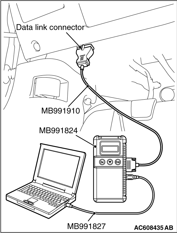
- MB991958 Scan Tool (M.U.T.-III Sub Assembly)
- MB991824: Vehicle Communication Interface (V.C.I.)
- MB991827 M.U.T.-III USB Cable
- MB991910 M.U.T.-III Main Harness A (Vehicles with CAN communication system)
|
|
|
Check the ignition power supply voltage.
|
|
(1)
| caution |
To prevent damage to scan tool MB991958, always turn the ignition switch to the "LOCK" (OFF) position before connecting or disconnecting scan tool MB991958.
|
Connect scan tool MB991958. Refer to "How to connect the Scan Tool (M.U.T.-III)  ." ."
(2)Check the ETACS data list.
- Turn the ignition switch to the "ON" position.
|
|
Item No.
|
Item name
|
Normal condition
|
Item 254
|
IG voltage
|
Approximately 12 volts (battery positive voltage)
|
|
(3)Turn the ignition switch to the "LOCK" (OFF) position.
Q.
Do the scan tool MB991958 display the item "IG voltage" is normal condition?
 Go to Step 4. Go to Step 4.
 Go to Step 2. Go to Step 2.
|
|
|
Q.
Is the battery in good condition?
|
|
|
Charge or replace the battery.
|
|
|
|
|
|
Refer to GROUP 16 - Output Current Test .
|
|
|
Q.
Is the charging system in good condition?
|
|
|
Refer to GROUP 54A, Diagnosis - Inspection Procedure 2 "ETACS-ECU does not receive any signal from the ignition switch (IG1)" .
|
|
|
|
|
|
Repair or replace the charging system component(s).
|
|
|
|
|
|
Check again if the DTC is set to the ETACS-ECU.
|
|
|
(2)Turn the ignition switch from "LOCK" (OFF) position to "ON" position.
|
|
|
(4)Turn the ignition switch to the "LOCK" (OFF) position.
|
|
|
The trouble can be an intermittent malfunction (Refer to GROUP 00, How to Cope with Intermittent Malfunction ).
|
|
|
|
![[Previous]](../../../buttons/fprev.png)
![[Next]](../../../buttons/fnext.png)
)
)
)