![[Previous]](../../../buttons/fprev.png)
![[Next]](../../../buttons/fnext.png)
DTC B210A: +B power supply (low input)
DTC B210B: +B power supply (high input)
| caution |
Before replacing the ECU, ensure that the input and output signal circuits are normal.
|
TROUBLE JUDGMENT
The ETACS-ECU sets DTC B210A if the power supply fuse (IOD fuse) voltage decreases to the specified value or less, and sets DTC B210B if the power supply fuse voltage increases to the specified value or more. However, when the status returns to normal, the ETACS-ECU automatically erases DTCs B210A and B210B.
TECHNICAL DESCRIPTION (COMMENT)
The power supply fuse (IOD fuse) or the ETACS-ECU may have a problem.
TROUBLESHOOTING HINTS
- The power supply fuse (IOD fuse) may be defective.
- The ETACS-ECU may be defective.
- The battery may be defective.
- The alternator may be defective.
- The wiring harness or connectors may have loose, corroded, or damaged terminals, or terminals pushed back in the connector
|
|
Required Special Tools:
- MB991223: Harness Set
- MB992006: Extra Fine Probe
- MB991958 Scan Tool (M.U.T.-III Sub Assembly)
- MB991824: Vehicle Communication Interface (V.C.I.)
- MB991827 M.U.T.-III USB Cable
- MB991910 M.U.T.-III Main Harness A (Vehicles with CAN communication system)
|
|
|
STEP 1. Power supply fuse check
|
|
|
Q.
Is the fuse in good condition?
|
|
|
 Go to Step 3. Go to Step 3.
|
|
|
|
|
|
 Go to Step 2. Go to Step 2.
|
|
|
|
|
|
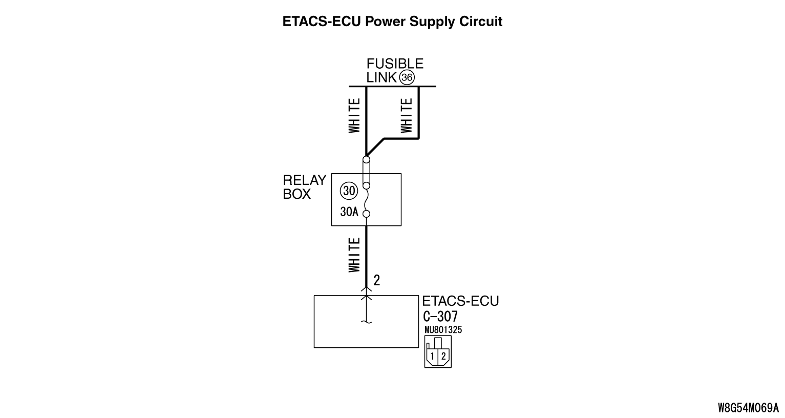
STEP 2. Check the wiring harness between C-307 ETACS-ECU connector and fuse No. 30.
|
|
|
Check the power supply line for short circuit.
|
|
|
Q.
Is the check result normal?
|
|
|
Replace the fuse No.30.
|
|
|
|
|
|
The short circuit may be present in the power supply circuit. Check the wiring harness between the C-307 ETACS-ECU connector terminal No. 2 and fuse No.30. Repair the wiring harness if necessary, and replace fuse No.30.
|
|
|
|
|
|
Refer to  . .
|
|
|
Q.
Is the battery in good condition?
|
|
|
Go to Step 4.
|
|
|
|
|
|
Charge or replace the battery.
|
|
|
|
|
|
STEP 4. Charging system check
|
|
|
Refer to GROUP 16 - Output Current Test .
|
|
|
Q.
Is the charging system in good condition?
|
|
|
Go to Step 5.
|
|
|
|
|
|
Repair or replace the charging system component(s).
|
|
|
|
|
|
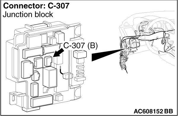
STEP 5. Check ETACS-ECU connector C-307 for loose, corroded or damaged terminals, or terminals pushed back in the connector.
|
|
|
Q.
Is ETACS-ECU connector C-307 in good condition?
|
|
|
Go to Step 6.
|
|
|
|
|
|
Repair or replace the component(s). Refer to GROUP 00E, Harness Connector Inspection .
|
|
|
|
|
|
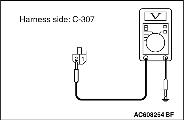
STEP 6. Check the battery power supply circuit to the ETACS-ECU. Measure the voltage at ETACS-ECU connector C-307.
|
|
|
(1)Disconnect ETACS-ECU connector C-307 and measure the voltage available at the wiring harness side of the connector.
|
|
(2)Measure the voltage between terminal 2 and ground.
- The voltage should measure approximately 12 volts (battery positive voltage).
Q.
Is the measured voltage approximately 12 volts (battery positive voltage)?
Go to Step 8.
Go to Step 7.
|
|
|
STEP 7. Check the wiring harness between ETACS-ECU connector C-307 (terminal 2) and the fusible link (36).
|
|
|
Check the power supply line for open circuit.
|
|
|
Q.
Is the wiring harness between ETACS-ECU connector C-307 (terminal 2) and the fusible link (36) in good condition?
|
|
|
No action is necessary and testing is complete.
|
|
|
|
|
|
The wiring harness may be damaged or the connector(s) may have loose, corroded or damaged terminals, or terminals pushed back in the connector. Repair the wiring harness as necessary.
|
|
|
|
|
|
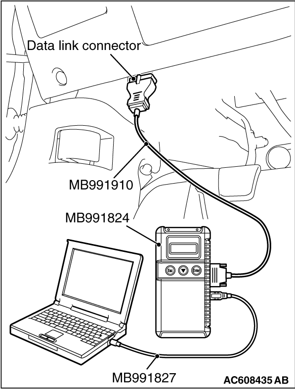
STEP 8. Using scan tool MB991958, check data list.
|
|
|
Check the power supply fuse voltage.
|
|
(1)
| caution |
To prevent damage to scan tool MB991958, always turn the ignition switch to the "LOCK" (OFF) position before connecting or disconnecting scan tool MB991958.
|
Connect scan tool MB991958. Refer to "How to connect the Scan Tool (M.U.T.-III) ."
(2)Check the ETACS data list.
- Turn the ignition switch to the "LOCK" (OFF) position.
|
|
Item No.
|
Item name
|
Normal condition
|
Item 253
|
Voltage sensing of IOD Line
|
Approximately 12 volts (battery positive voltage)
|
|
Q.
Do the scan tool MB991958 display the item "voltage sensing of IOD Line" is normal condition?
Go to Step 9.
Replace the ETACS-ECU.
|
|
|
STEP 9. Recheck for diagnostic trouble code.
|
|
|
Check again if the DTC is set to the ETACS-ECU.
|
|
|
(2)Turn the ignition switch from "LOCK" (OFF) position to "ON" position.
|
|
|
(4)Turn the ignition switch to the "LOCK" (OFF) position.
|
|
|
Replace the ETACS-ECU.
|
|
|
|
|
|
The trouble can be an intermittent malfunction (Refer to GROUP 00, How to Cope with Intermittent Malfunction ).
|
|
|
|
)
)
)
)