|
|
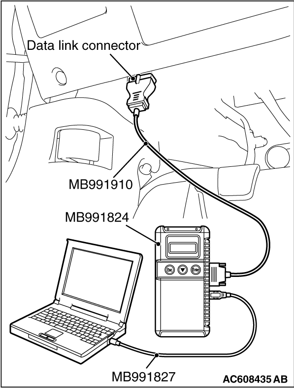
Required Special Tools:
- MB991958: Scan Tool (M.U.T.-III Sub Assembly)
- MB991824: Vehicle Communication Interface (V.C.I.)
- MB991827: M.U.T.-III USB Cable
- MB991910: M.U.T.-III Main Harness A (Vehicles with CAN communication system)
|
|
(1)
| caution |
To prevent damage to scan tool MB991958, always turn the ignition switch to the "LOCK"
(OFF) position before connecting or disconnecting scan tool MB991958.
|
Connect scan tool MB991958. Refer to "How to connect the Scan Tool (M.U.T.-III)  ." ."
(2)Turn the ignition switch to the "ON" position.
(3)Diagnose the CAN bus line.
(4)Turn the ignition switch to the "LOCK" (OFF) position.
Q.
Is the CAN bus line found to be normal?
 Go to Step 2. Go to Step 2.
 Repair the CAN bus line (Refer to GROUP 54C, Diagnosis ). Repair the CAN bus line (Refer to GROUP 54C, Diagnosis ).
|
|
|
Check the variant code written to the ETACS-ECU, and check whether it matches the ECU
connected to the CAN-B line.
|
|
|
Q.
Is the check result normal?
|
|
|
Make a correction so that the ECU connected to the CAN-B line matches with the
variant code information, and then go to Step 3.
|
|
|
|
|
|
Check again if the DTC is set to the ETACS-ECU.
|
|
|
(2)Turn the ignition switch from "LOCK" (OFF) position to "ON" position.
|
|
|
(4)Turn the ignition switch to the "LOCK" (OFF) position.
|
|
|
This diagnosis is complete.
|
|
|
|
![[Previous]](../../../buttons/fprev.png)
![[Next]](../../../buttons/fnext.png)
)