![[Previous]](../../../buttons/fprev.png)
![[Next]](../../../buttons/fnext.png)
Inspection Procedure 1: Hands free cellular phone system does not work normally.
| caution |
Before replacing the module, ensure that the power supply circuit, the ground circuit and the communication circuit are normal.
|
FUNCTION
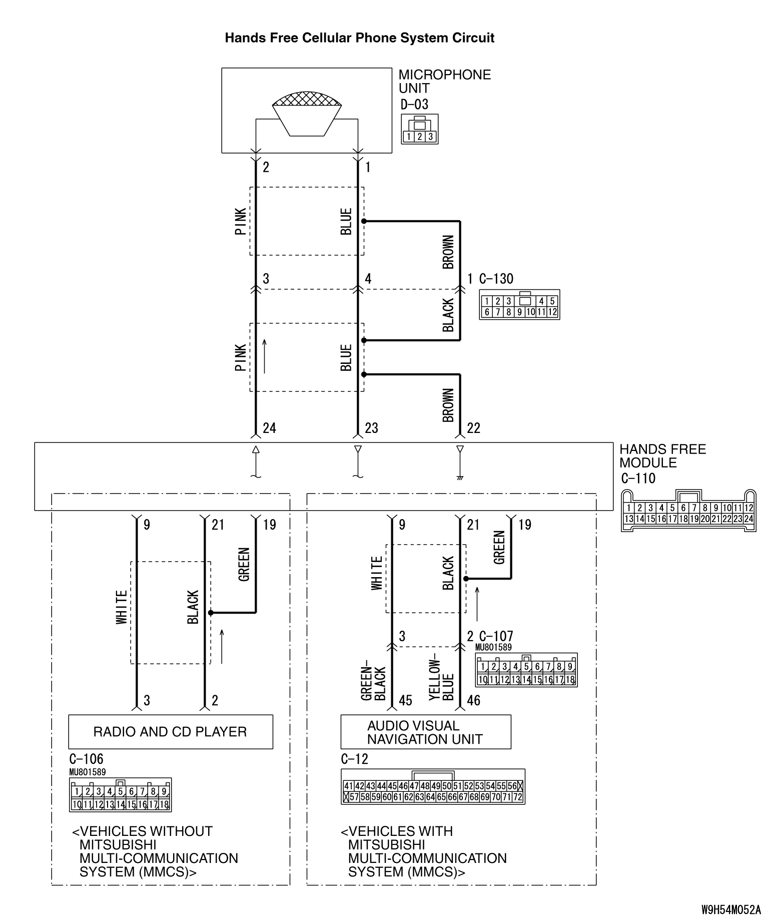
During the conversation with the hands free cellular phone system, the signal of speaker’s voice is transmitted from the microphone unit to the hands free module. Then the signal is transmitted from the hands free module to the cellular phone. The voice of other party is transmitted from the cellular phone to the hands-free module. Then, the voice is transmitted from the hands free module to the radio and CD player <vehicles without MMCS> or audio visual navigation unit <vehicles with MMCS>, and output from the speaker.
TROUBLE JUDGMENT CONDITIONS
If the hands free cellular phone system cannot be used normally, the hands free module, microphone unit, steering wheel voice control switch, or radio and CD player <vehicles without MMCS> or audio visual navigation unit <vehicles with MMCS> may be defective.
TROUBLESHOOTING HINTS
- Malfunction of the hands free module
- Malfunction of the microphone unit
- Malfunction of the steering wheel voice control switch
- Malfunction of the radio and CD player <vehicles without MMCS> or audio visual navigation unit <vehicles with MMCS>
- Damaged harness wires and connectors
|
|
Required Special Tools:
- MB991223: Harness Set
- MB992006: Extra Fine Probe
- MB991958: Scan Tool (M.U.T.-III Sub Assembly)
- MB991824: Vehicles Communication Interface (V.C.I.)
- MB991827: M.U.T.-III USB Cable
- MB991910: M.U.T.-III Main Harness A (Vehicles with CAN communication system)
|
|
|
STEP 1. Check the cellular phone.
|
|
|
Check that the cellular phone can be used normally as a unit.
|
|
|
Q.
Is it possible to use the cellular phone normally?
|
|
|
 Go to Step 2. Go to Step 2.
|
|
|
|
|
|
 Repair or replace the cellular phone. Repair or replace the cellular phone.
|
|
|
|
|
|
STEP 2. Temporarily replace the cellular phone, and check the trouble symptom.
|
|
|
Temporarily register a separate Bluetooth supported cellular phone, and check that the hands free cellular phone system operates normally.
|
|
|
Q.
Is the normal conversation possible with the hands-free system?
|
|
|
Ask the customer to have the cellular phone repaired or replaced. Then, delete the temporarily registered cellular phone. Once the customer prepares the normally working cellular phone, register the cellular phone to the hands free module. (Refer to  .) .)
|
|
|
|
|
|
Go to Step 3.
|
|
|
|
|
|
STEP 3. Using scan tool MB991958, diagnose the CAN bus line.
|
|
(1)
| caution |
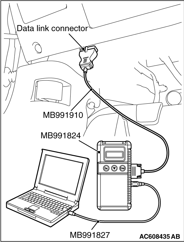
To prevent damage to scan tool MB991958, always turn the ignition switch to the "LOCK" (OFF) position before connecting or disconnecting scan tool MB991958.
|
Connect scan tool MB991958. Refer to "How to connect the Scan Tool (M.U.T.-III) ."
(2)Turn the ignition switch to the "ON" position.
(3)Diagnose the CAN bus line.
(4)Turn the ignition switch to "LOCK" (OFF) position.
Q.
Is the CAN bus line found to be normal?
Go to Step 4.
Repair the CAN bus line (Refer to GROUP 54C, Diagnosis ).
|
|
|
STEP 4. Check hands-free module connector C-110 for loose, corroded or damaged terminals, or terminals pushed back in the connector.
|
|
|
Q.
Are hands free module connector C-110 in good condition?
|
|
|
Go to Step 5.
|
|
|
|
|
|
Repair or replace the damaged component(s). Refer to GROUP 00E, Harness Connector Inspection .
|
|
|
|
|
|
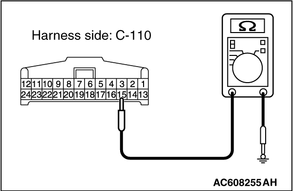
STEP 5. Check the ground circuit to the hands free module. Measure the resistance at hands free module connector C-110.
|
|
|
(1)Disconnect hands free module connector C-110, and measure at the wiring harness side.
|
|
(2)Measure resistance between terminal 15 and ground.
OK: The resistance should be 2 ohm or less.
Q.
Is the measured resistance 2 ohms or less?
Go to Step 7.
Go to Step 6.
|
|
|
STEP 6. Check the wiring harness between hands-free module connector C-110 (terminal 15) and ground.
|
|
|
- Check the ground wire for open circuit.
|
|
|
Q.
Is the wiring harness between hands-free module connector C-110 (terminal 15) and ground in good condition?
|
|
|
The trouble can be an intermittent malfunction (Refer to GROUP 00, How to use Troubleshooting/inspection Service Points, How to Cope with Intermittent Malfunction ).
|
|
|
|
|
|
The wiring harness may be damaged or the connector(s) may have loose, corroded or damaged terminals, or terminals pushed back in the connector. Repair the wiring harness as necessary.
|
|
|
|
|
|
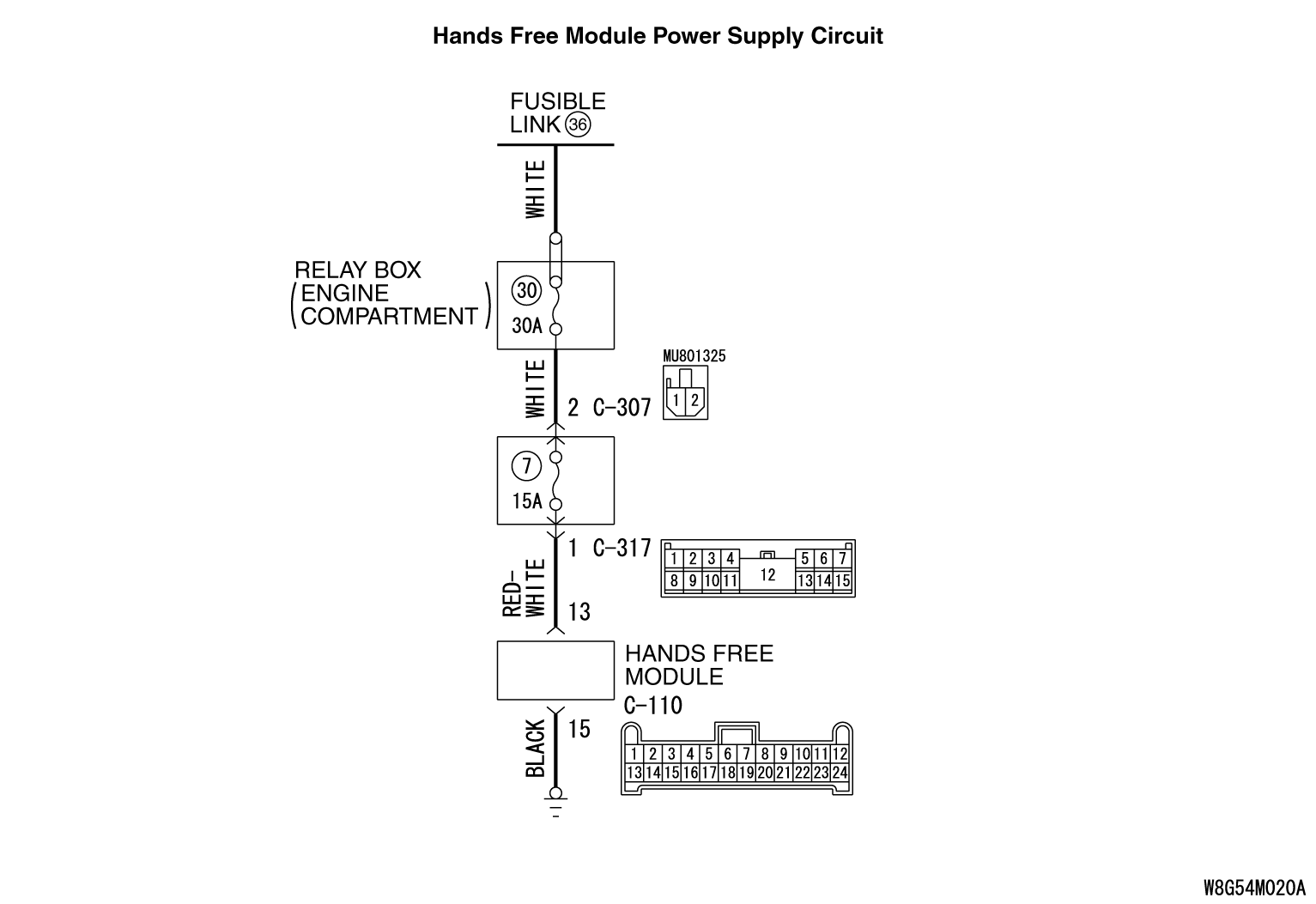
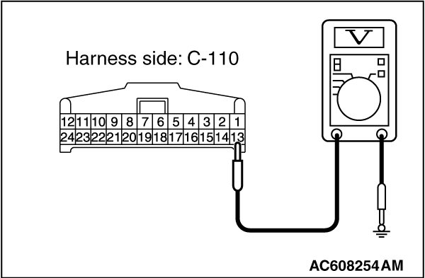
STEP 7. Check the power supply circuit to the hands-free module. Measure the voltage at hands free module connector C-110.
|
|
|
(1)Disconnect hands free module connector C-110, and measure the voltage available at the hands-free module side of the connector.
|
|
(2)Measure the voltage between terminal 13 and ground.
OK: The voltage should measure approximately 12 volts (battery positive voltage).
Q.
Is the measured voltage approximately 12 volts (battery positive voltage)?
Go to Step 9.
Go to Step 8.
|
|
|
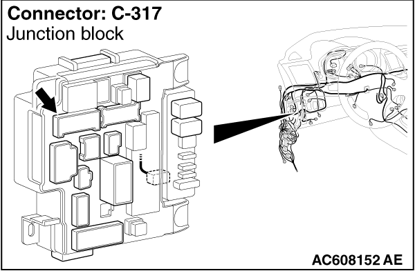
STEP 8. Check the wiring harness between hands-free module connector C-110 (terminal 13) and ETACS-ECU connector C-317 (terminal 1).
|
|
|
- Check the power supply line for open circuit and short circuit.
|
|
|
Q.
Is the wiring harness between hands-free module connector C-110 (terminal 13) and ETACS-ECU connector C-317 (terminal 1) in good condition?
|
|
|
The trouble can be an intermittent malfunction (Refer to GROUP 00, How to use Troubleshooting/inspection Service Points, How to Cope with Intermittent Malfunction ).
|
|
|
|
|
|
The wiring harness may be damaged or the connector(s) may have loose, corroded or damaged terminals, or terminals pushed back in the connector. Repair the wiring harness as necessary.
|
|
|
|
|
|
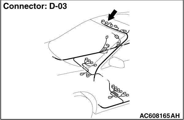
STEP 9. Check microphone unit connector D-03 for loose, corroded or damaged terminals, or terminals pushed back in the connector.
|
|
|
Q.
Is microphone unit connector D-03 in good condition?
|
|
|
Go to Step 10.
|
|
|
|
|
|
Repair or replace the damaged component(s). Refer to GROUP 00E, Harness Connector Inspection .
|
|
|
|
|
|
STEP 10. Check the wiring harness between hands free module connector C-110 and microphone unit connector D-03.
|
|
|
- Check the communication lines for open circuit and short circuit.
|
|
|
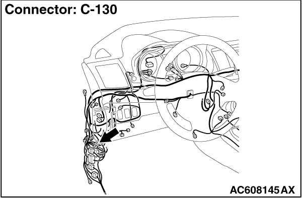
(1)Disconnect hands-free module connector C-110 and microphone unit connector D-03, and check the wiring harness.
| note |
Also check intermediate connector C-130 for loose, corroded, or damaged terminals, or terminals pushed back in the connector. If intermediate connector C-130 is damaged, repair or replace the connector as described in GROUP 00E, Harness Connector Inspection .
|
|
|
|
(2)Check the wiring harness between hands free module connector C-110 (terminal 1) and microphone unit connector D-03 (terminal 23)
|
|
|
(3)Check the wiring harness between hands-free module connector C-110 (terminal 2) and microphone unit connector D-03 (terminal 24)
|
|
|
Q.
Is the wiring harness between hands free module connector C-110 and microphone unit connector D-03 in good condition?
|
|
|
Go to Step 11.
|
|
|
|
|
|
The wiring harness may be damaged or the connector(s) may have loose, corroded or damaged terminals, or terminals pushed back in the connector. Repair the wiring harness as necessary.
|
|
|
|
|
|
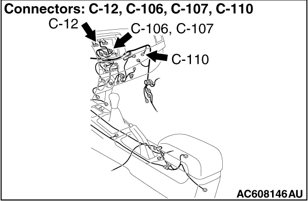
STEP 11. Check radio and CD player connector C-106 <vehicles without MMCS> or audio visual navigation unit connector C-12 <vehicles with MMCS> for loose, corroded or damaged terminals, or terminals pushed back in the connector.
|
|
|
Q.
Is radio and CD player C-106 <vehicles without MMCS> or audio visual navigation unit connector C-12 <vehicles with MMCS> in good condition?
|
|
|
Go to Step 12.
|
|
|
|
|
|
Repair or replace the damaged component(s). Refer to GROUP 00E, Harness Connector Inspection .
|
|
|
|
|
|
STEP 12. Check the wiring harness between hands free module connector C-110 and radio and CD player connector C-106 <vehicles without MMCS> or audio visual navigation unit connector C-12 <vehicles with MMCS>.
|
|
|
- Check the communication lines for open circuit and short circuit.
|
|
|
(1)Disconnect hands-free module connector C-110 and radio and CD player C-106 <vehicles without MMCS> or audio visual navigation unit connector C-12 <vehicles with MMCS>, and check the wiring harness.
| note |
Also check intermediate connector C-107 for loose, corroded, or damaged terminals, or terminals pushed back in the connector. If intermediate connector C-107 is damaged, repair or replace the connector as described in GROUP 00E, Harness Connector Inspection . <vehicles with MMCS>
|
|
|
|
(2)Check the wiring harness between hands free module connector C-110 (terminal 9) and radio and CD player or CD changer connector C-106 (terminal 3) <vehicles without MMCS>
|
|
|
(3)Check the wiring harness between hands free module connector C-110 (terminal 21) and radio and CD player or CD changer connector C-106 (terminal 2) <vehicles without MMCS>
|
|
|
(4)Check the wiring harness between hands free module connector C-110 (terminal 9) and audio visual navigation unit connector C-12 (terminal 45) <vehicles with MMCS>
|
|
|
(5)Check the wiring harness between hands free module connector C-110 (terminal 21) and audio visual navigation unit connector C-12 (terminal 46) <vehicles with MMCS>
|
|
|
Q.
Is the wiring harness between hands free module connector C-110 and radio and CD player connector C-106 <vehicles without MMCS> or audio visual navigation unit connector C-12 <vehicles with MMCS> in good condition?
|
|
|
Go to Step 13.
|
|
|
|
|
|
The wiring harness may be damaged or the connector(s) may have loose, corroded or damaged terminals, or terminals pushed back in the connector. Repair the wiring harness as necessary.
|
|
|
|
|
|
STEP 13. Temporarily replace the microphone unit, and check the trouble symptom.
|
|
|
Check that the normal conversation is possible with the hands free cellular phone system.
|
|
|
Q.
Is the normal conversation possible with the hands free cellular phone system?
|
|
|
Replace the microphone unit.
|
|
|
|
|
|
Go to Step 14.
|
|
|
|
|
|
STEP 14. Temporarily replace the hands ree module, and check the trouble symptom.
|
|
|
Check that the normal conversation is possible with the hands free cellular phone system.
|
|
|
Q.
Is the normal conversation possible with the hands free cellular phone system?
|
|
|
Replace the hands free module.
|
|
|
|
|
|
Replace the radio and CD player <vehicles without MMCS> or audio visual navigation unit <vehicles with MMCS>.
|
|
|
|
)
)
)
)
)
)
)
)
)