![[Previous]](../../../buttons/fprev.png)
![[Next]](../../../buttons/fnext.png)
DTC U0151: SRS-ECU CAN timeout
| caution |
- If DTC U0151 is set, be sure to diagnose the CAN bus line.
- When replacing the ECU, always check that the communication circuit is normal.
|
DIAGNOSTIC FUNCTION
If the signal from SRS-ECU cannot be received, the combination meter sets DTC U0151.
JUDGMENT CRITERIA
With the ignition switch in the ON position, system voltage between 10-16 volts (data from ETACS-ECU), power supply fuse (IOD fuse) is OK, or odometer value is 80.5 km (50 miles) or more, and the communication with SRS-ECU cannot be established for 2,500 ms or more, the combination meter determines that a problem has occurred.
TROUBLESHOOTING HINTS
- The CAN bus line may be defective
- The SRS-ECU may be defective
- The combination meter may be defective
|
|
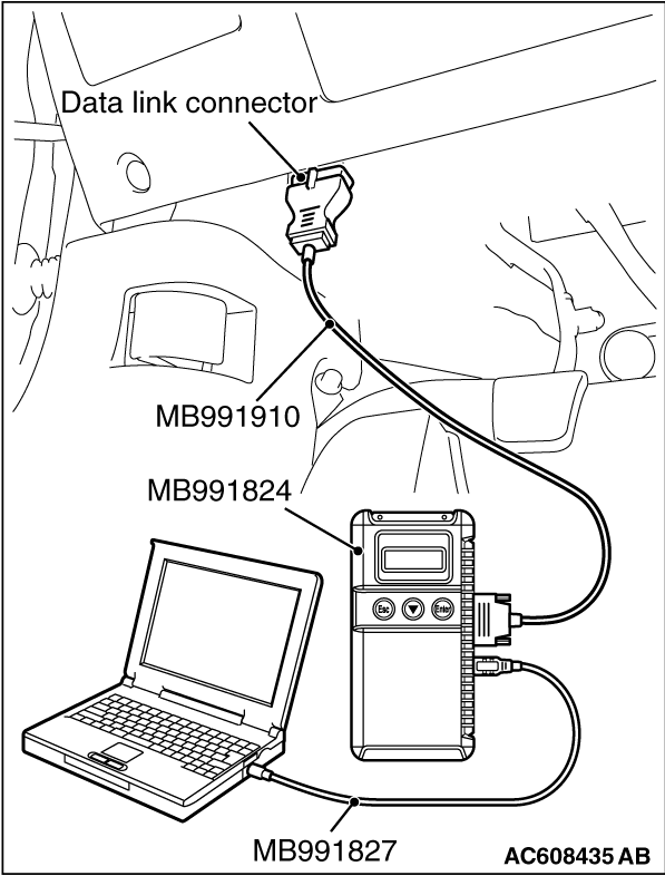
Required Special Tools:
- MB991958: Scan Tool (M.U.T.-III Sub Assembly)
- MB991824: Vehicles Communication Interface (V.C.I.)
- MB991827: M.U.T.-III USB Cable
- MB991910: M.U.T.-III Main Harness A (Vehicles with CAN communication system)
|
|
|
STEP 1. Using scan tool MB991958, diagnose the CAN bus line
|
|
(1)
| caution |
To prevent damage to scan tool MB991958, always turn the ignition switch to the "LOCK" (OFF) position before connecting or disconnecting scan tool MB991958.
|
Connect scan tool MB991958. Refer to "How to connect the Scan Tool (M.U.T.-III)  ." ."
(2)Turn the ignition switch to the "ON" position.
(3)Diagnose the CAN bus line.
(4)Turn the ignition switch to the "LOCK" (OFF) position.
Q.
Is the CAN bus line found to be normal?
 Go to Step 2. Go to Step 2.
 Repair the CAN bus line (Refer to GROUP 54C, Diagnosis ). Repair the CAN bus line (Refer to GROUP 54C, Diagnosis ).
|
|
|
STEP 2. Using scan tool MB991958, read the SRS-ECU diagnostic trouble code
|
|
|
Check again if the DTC is set to the SRS-ECU.
|
|
|
Troubleshoot the SRS (Refer to GROUP 52B, Troubleshooting ).
|
|
|
|
|
|
Go to Step 3.
|
|
|
|
|
|
STEP 3. Using scan tool MB991958, read the A/C-ECU diagnostic trouble code.
|
|
|
Check if the DTC U0151 is set to the A/C-ECU.
|
|
|
Go to Step 4.
|
|
|
|
|
|
Go to Step 5.
|
|
|
|
|
|
STEP 4. Recheck for diagnostic trouble code.
|
|
|
Check again if the DTC is set to the combination meter.
|
|
|
(2)Turn the ignition switch from "LOCK" (OFF) position to "ON" position.
|
|
|
(4)Turn the ignition switch to the "LOCK" (OFF) position.
|
|
|
Replace the SRS-ECU.
|
|
|
|
|
|
The trouble can be an intermittent malfunction such as a poor connection or open circuit in the CAN bus lines between the SRS-ECU and the combination meter (Refer to GROUP 00, How to Cope with Intermittent Malfunction ).
|
|
|
|
|
|
STEP 5. Recheck for diagnostic trouble code.
|
|
|
Check again if the DTC is set to the combination meter.
|
|
|
(2)Turn the ignition switch from "LOCK" (OFF) position to "ON" position.
|
|
|
(4)Turn the ignition switch to the "LOCK" (OFF) position.
|
|
|
Replace the combination meter.
|
|
|
|
|
|
The trouble can be an intermittent malfunction such as a poor connection or open circuit in the CAN bus lines between the SRS-ECU and the combination meter (Refer to GROUP 00, How to Cope with Intermittent Malfunction ).
|
|
|
|
)