|
|
Required Special Tools:
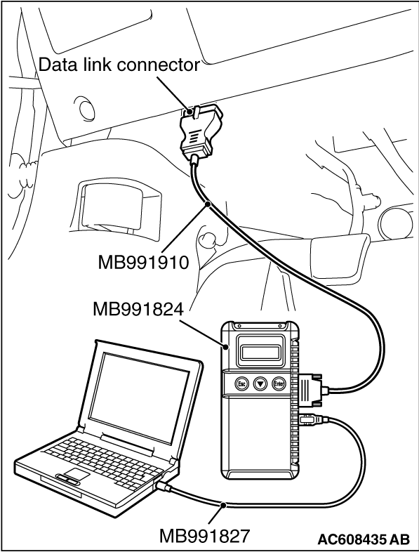
- MB991958: Scan Tool (M.U.T.-III Sub Assembly)
- MB991824: Vehicle Communication Interface (V.C.I.)
- MB991827: M.U.T.-III USB Cable
- MB991910: M.U.T.-III Main Harness A (Vehicles with CAN communication system)
|
|
|
Check whether the left turn-signal light illuminates normally.
|
|
|
Q.
Is the check result normal?
|
|
|
 Replace the bulb of turn-signal light which does not illuminate. Replace the bulb of turn-signal light which does not illuminate.
|
|
|
|
|
|
Q.
Are headlight assembly (LH) connector A-31 <front>, side turn-signal light (LH)
connector A-08 <side>, rear combination light (LH) connector F-20 <rear>
in
good condition?
|
|
|
NO : Repair or replace the damaged component(s). Refer to GROUP 00E, Harness Connector
Inspection  . .
|
|
|
|
|
|
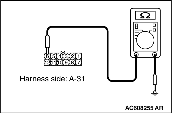
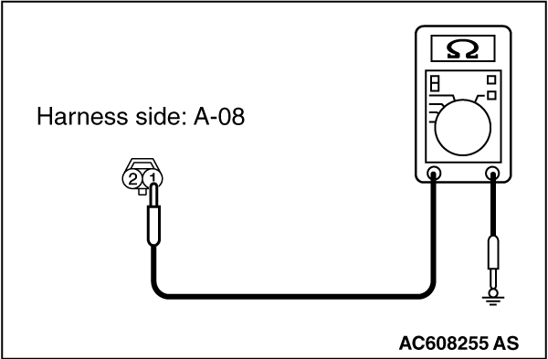
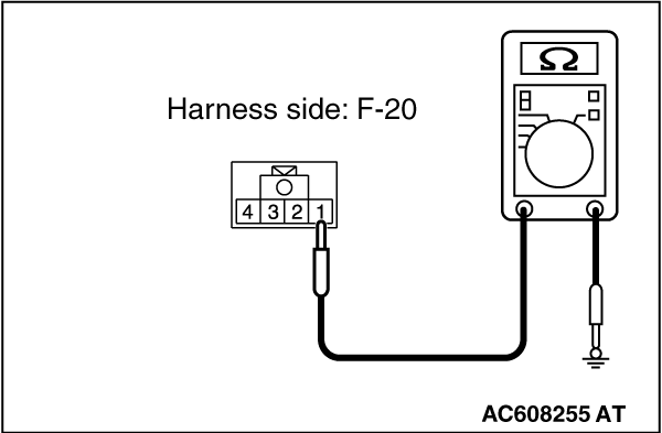
(1)Disconnect the connector, and measure at the wiring harness side.
|
|
(2)Measure the resistance between the connector terminal of light which does not illuminate
and ground.
- Measure the resistance between the headlight assembly (LH) connector A-31 (terminal 6)
and body ground. <Front>
- Measure the resistance between side turn-signal light (LH) connector A-08 (terminal 1)
and body ground. <Side>
- Measure the resistance between rear combination light (LH) connector F-20 (terminal 1)
and body ground. <Rear>
OK: The measured value should be 2 Ω
or less.
Q.
Does the measured resistance value correspond with this range?
 Go to Step 5. Go to Step 5.
Go to Step 4.
|
|
|
- Check the ground wires for open circuit.
|
|
|
Q.
Are the wiring harness between headlight assembly (LH) connector A-31 (terminal 6) <front>,
side turn-signal light (LH) connector A-08 (terminal 1) <side>, rear combination
light (LH) connector F-20 (terminal 1) <rear>
and ground in good condition?
|
|
|
The wiring harness may be damaged or the connector(s) may have loose, corroded
or damaged terminals, or terminals pushed back in the connector. Repair the wiring harness as
necessary. Verify that the headlights illuminate normally.
|
|
|
|
|
|
Q.
Are ETACS-ECU connectors C-304 <front or side> and C-311 <rear>
in
good condition?
|
|
|
Replace the bulb(s) of the light that does not illuminate.
|
|
|
|
|
|
- Check the power supply line for open circuit.
|
|
|
Q.
Are the wiring harness between headlight assembly (LH) connector A-31 (terminal 3) <front>,
side turn-signal light (LH) connector A-08 (terminal 2) <side>, rear combination
light (LH) connector F-20 (terminal 2) <rear>
and ETACS-ECU connector C-304 (terminal
9) <front or side> or C-311 (terminal 18) <rear>
in good condition?
|
|
|
The wiring harness may be damaged or the connector(s) may have loose, corroded
or damaged terminals, or terminals pushed back in the connector. Repair the wiring harness as
necessary. Verify that the headlights illuminate normally.
|
|
|
|
|
(1)
| caution |
To prevent damage to scan tool MB991958, always turn the ignition switch
to the "LOCK" (OFF) position before connecting or disconnecting scan tool MB991958.
|
Connect scan tool MB991958. Refer to "How to connect scan tool ."
(2)Turn the ignition switch to the "ON" position.
(3)Erase the DTC.
(4)Turn the ignition switch from "LOCK" (OFF) position to "ON" position.
(5)Check whether the ETACS-ECU DTC is set.
Q.
Is the DTC set?
Replace the ETACS-ECU.
The procedure is complete.
|
![[Previous]](../../../buttons/fprev.png)
![[Next]](../../../buttons/fnext.png)
)
)
)
)
)
)
)
)
)