|
|
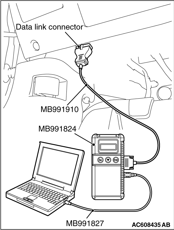
Required Special Tools:
- MB991958: Scan Tool (M.U.T.-III Sub Assembly)
- MB991824: Vehicles Communication Interface (V.C.I.)
- MB991827: M.U.T.-III USB Cable
- MB991910: M.U.T.-III Main Harness A (Vehicles with CAN communication system)
|
|
|
(1)Turn the ignition switch to the "ON" position.
|
|
|
(2)Diagnose the CAN bus line.
|
|
|
(3)Turn the ignition switch to the "LOCK" (OFF) position.
|
|
|
Q.
Is the CAN bus line found to be normal?
|
|
|
 Repair the CAN bus line (Refer to GROUP 54C, Diagnosis Repair the CAN bus line (Refer to GROUP 54C, Diagnosis  ). ).
|
|
|
|
|
|
Check again if the DTC is set to the occupant classification-ECU.
|
|
(1)
| caution |
To prevent damage to scan tool MB991958, always turn the ignition switch to the "LOCK" (OFF)
position before connecting or disconnecting scan tool MB991958.
|
Connect scan tool MB991958. Refer to "How to connect the scan tool ."
(2)Turn the ignition switch to the "ON" position.
(3)Check if DTC is set.
(4)Turn the ignition switch to the "LOCK" (OFF) position.
Q.
Is the DTC set?
 Replace the front seat cushion frame (RH) (Refer to GROUP 52A, Front Seat Assembly ) <Except RALLIART>
or replace the slide adjuster (RH) (Refer to GROUP 52A, Front Seat Assembly ) <RALLIART>. Replace the front seat cushion frame (RH) (Refer to GROUP 52A, Front Seat Assembly ) <Except RALLIART>
or replace the slide adjuster (RH) (Refer to GROUP 52A, Front Seat Assembly ) <RALLIART>.
There is an intermittent malfunction such as poor engaged connector(s) or open
circuit (Refer to GROUP 00, How to Cope with Intermittent Malfunction ).
|
![[Previous]](../../../buttons/fprev.png)
![[Next]](../../../buttons/fnext.png)
)